did yo make sure it was properly connected on both ends. Cords are WAY off topic.
Last edited by a moderator:
The point here was for Grimberg to possibly try if a good power cable would help with the harsness of the BassZillas. Many seem to think it should not be the amps so it may be worth a try. Yes, no cable debate needed here... 😎
Hi people,
Sorry if I overlooked some previous post but can anybody direct me to a reliable source for matched IRFP parts...really don´t trust myself to do the matching. Going to build 2 monoblocks with an Impasse pre.
Also, Zen Mod, if you´re listening...you mention some posts back something about motor rus caps for bypassing the PSU. I have a bunch of really nice ASC 100uF caps. Would it be worthwhile to try them? Right next to the PSU I suppose. Suggestions are welcome...
Thank you!
Thanks for the tip on the mosfets.
Sorry, again as I still haven´t read the whole thread.
Elco as in Elma Silmic? CRC values? any other than Papa´s schematic 2*15000uF 25V / 4*0.47R / 2*15000uF 25V ?
Would 100uF Motor Runs be OK for each of the c1-c4 caps. If I try this I better get a big case and get some workout going. It will be a heavy MF...
Thanks for the patience... 😀
Last edited:
.....
Elco as in Elma Silmic? CRC values? any other than Papa´s schematic 2*15000uF 25V / 4*0.47R / 2*15000uF 25V ?
Would 100uF Motor Runs be OK for each of the c1-c4 caps. If I try this I better get a big case and get some workout going. It will be a heavy MF...
........ 😀
elco as electrolytic
regarding motor-runs - mF is mF ; you can't replace big electrolytics with (any) solid cap , due to capacitance demands
but , as I said numerous times , they're great as bypass caps ..... meaning - put those instead of usual sissy ones ...... small both in value and size
Member
Joined 2009
Paid Member
really don´t trust myself to do the matching.
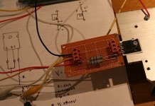
You would be surprised how easy it is and once finished you'll be more confident about building the amp yourself too.
I just followed Nelson's circuit on a small piece of proto-board and life was easy. And I have the board to use again as and when it is needed.
Attachments
elco as electrolytic
Right...
regarding motor-runs - mF is mF ; you can't replace big electrolytics with (any) solid cap , due to capacitance demands
Well, 100uF Motor Run is not that for from 220uF required for C1-C4 and I thought you said solo motor run for for local decoupling... were you referring to those? Is no biggie really, I´m sure it´s an splendid amp as designed but having all of those caps around is tempting 🙄
You would be surprised how easy it is and once finished you'll be more confident about building the amp yourself too.
Looks easy. Thank you!
well - you said C1-C4 , but I'm lost without ref. to exact schm. ( too many times mistakes were made with just taking things for granted) ........ so I didn't know which ones ....
yup - feel free to substitute 100uF motorrun instead of sissy 220uF elco 😉
yup - feel free to substitute 100uF motorrun instead of sissy 220uF elco 😉
well - you said C1-C4 , but I'm lost without ref. to exact schm. ( too many times mistakes were made with just taking things for granted) ........ so I didn't know which ones ....
yup - feel free to substitute 100uF motorrun instead of sissy 220uF elco 😉
Yes, my bad...yippie on the Motor Runs! 8 per monoblock, 4 bypass for PSU and 4 instead of the 220uF, as close as possible to the boards I assume...
I don´t know if I´ll be brave enough to try but if I do this is going to look a lot like a tube amp (not that I don´t like that...) 😎
Thanks for the tips!
🙂

Calling Mr. Pass...
Dear Mr. Pass,
I apologize for the timing, but I just saw your diy messages to me from back in Feb 2014. Unfortunately, I had an old email address that you tried to reply to and obviously, I rarely check it!
I have updated my email address now so it is now current. I would be very pleased to have you contact me offline as I have oh so many questions!
😉
Cheers and thanks
Gary
Pf contributor
F4 problem
Hi guys, I have a problem with two DIY F4's and hope you can point me in the right direction. A friend of mine (a retired radar engineer) put them together for me. He biased the F4's to 250mV and the sinks of the Modushop 300mm 3U enclosures stabilize at about 55C. Source of parts A few years ago I bought F4 PCB's from the diyaudio store and F4 semiconductor kits from tech-diy. All other parts were sourced from digikey, mouser and farnell (i.e. no ebay junk). The power supply (see attached) is similar to the standard F4/BA PS. I inserted a single F4 (stereo) into the system in my study but the sound is not good. There is plenty of unrefined/harsh bass and highs but not much mid. Overall it sounds more like cheap hifi than the F4 should. Preamp gain BTW is not the issue (volume pot at 12 o'clock is loud) and the system sounded great before I replaced my DIY Aleph J (volume pot a 9 o'clock is loud) with the F4. Replacing the F4 by the Aleph J brings back the magic. BTW: It is not that I miss the Aleph sound (I know the F4 is supposed to sound different), it just sounds bad. I have used other power amps in this system and even cheap ones sound better than the F4 does at the moment. Thinking it might be mismatch, I installed the second F4 in my main system where it replaced (a Pass Labs original) Aleph 3 that I use for mid/high on Magnepan MG3A's. The Maggies are insensitive, so I knew that I would not be able to play them loud. Forget about playing it loud, it just sounds bad. Because the sound is bad from both F4's I have no idea what could be causing it. People have talked about fake JFETs from ebay in the past but I have not heard of people having trouble with those supplied by tech-diy. Before I take my F4's apart I hope you can give me some idea what to look for. Your help is appreciated. Thanks, Albert Edit: I cannot get carriage returns to work properly, sorry.
Hi guys, I have a problem with two DIY F4's and hope you can point me in the right direction. A friend of mine (a retired radar engineer) put them together for me. He biased the F4's to 250mV and the sinks of the Modushop 300mm 3U enclosures stabilize at about 55C. Source of parts A few years ago I bought F4 PCB's from the diyaudio store and F4 semiconductor kits from tech-diy. All other parts were sourced from digikey, mouser and farnell (i.e. no ebay junk). The power supply (see attached) is similar to the standard F4/BA PS. I inserted a single F4 (stereo) into the system in my study but the sound is not good. There is plenty of unrefined/harsh bass and highs but not much mid. Overall it sounds more like cheap hifi than the F4 should. Preamp gain BTW is not the issue (volume pot at 12 o'clock is loud) and the system sounded great before I replaced my DIY Aleph J (volume pot a 9 o'clock is loud) with the F4. Replacing the F4 by the Aleph J brings back the magic. BTW: It is not that I miss the Aleph sound (I know the F4 is supposed to sound different), it just sounds bad. I have used other power amps in this system and even cheap ones sound better than the F4 does at the moment. Thinking it might be mismatch, I installed the second F4 in my main system where it replaced (a Pass Labs original) Aleph 3 that I use for mid/high on Magnepan MG3A's. The Maggies are insensitive, so I knew that I would not be able to play them loud. Forget about playing it loud, it just sounds bad. Because the sound is bad from both F4's I have no idea what could be causing it. People have talked about fake JFETs from ebay in the past but I have not heard of people having trouble with those supplied by tech-diy. Before I take my F4's apart I hope you can give me some idea what to look for. Your help is appreciated. Thanks, Albert Edit: I cannot get carriage returns to work properly, sorry.
Attachments
Last edited:
What grade are the Jfets? you have to look on the transistor face.
Hi 6L6,
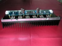
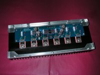
I am not sure of the grade. I think that at the time tech-diy mentioned on their website that they ran out of BL and supplied GR. I had a look at some old photo's my friend sent me while he was building them, but they do not show enough detail (see attached).
I will have to open up the enclosure but that is a bit of a problem (wheelchair user, I have to get someone to help me). Hope to find out in the next few days.
Thanks,
Albert
PS I think I have the cariage return issue sorted.
PPS I forgot to mention that both F4's are dead quiet. No hum or anything like that.
Attachments
Last edited:
If you are using GR Jfets, you can get a little more bias on them by reducing
R3 and R4 to 1 ohm instead of 10. Actually, you can just short R3 and R4,
but 1 ohm lets you sense the current if you want.
😎
R3 and R4 to 1 ohm instead of 10. Actually, you can just short R3 and R4,
but 1 ohm lets you sense the current if you want.
😎
mosfets are not soldered in. ?
Albert,
those pictures may not be of the completed boards, but if they are it looks like the N channel mosfets are not soldered in.
Albert,
those pictures may not be of the completed boards, but if they are it looks like the N channel mosfets are not soldered in.
Albert,
those pictures may not be of the completed boards, but if they are it looks like the N channel mosfets are not soldered in.
I agree, it looks to me also like it is not soldered in completely.
I agree, it looks to me also like it is not soldered in completely.
Hi guys, Thanks for the suggestion, but I am afraid the soldering is not the problem. These were old photo's my friend sent me while he was building them. The soldering was completed some time after the photo's were taken. Albert
- Home
- Amplifiers
- Pass Labs
- F4 power amplifier