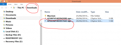
ascAnd its dot (as in full stop) asc. Just try that, it should show the files.
.asc
*.asc
all show no results.
My downloads goes to blank when I shut down the browser.
I downloaded the asc and used it to follow your instructions. I saved it when still in LTspice.
But it's not in the LTspice folders: examples, educational, jigs, etc.
How do I search My documents?
In the meantime I can download it again, until I can understand win7 and LTspice save features.
dos was so much easier.
used "save as" and there were some of the missing .asc files. 6 of them in My documents.
Why does win search not find them?
Last edited:
asc
.asc
*.asc
all show no results.
My downloads goes to blank when I shut down the browser.
I downloaded the asc and used it to follow your instructions. I saved it when still in LTspice.
But it's not in the LTspice folders: examples, educational, jigs, etc.
How do I search My documents?
Try this... the files were all named "Radford Preamp xxxxxxx" so just type Radford into W7's search box and see if it picks the file up. If it does then right click the file and look at "show file location" to see where it is.
OK 🙂 Here is the distortion at 5k loading (20kHz test).
That's R5 in my circuit, the 100k.
Sorry now i see it
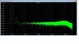
This is my fft for a 5K load ... it does not look nice as yours ... 😱
Just i do not like the wide peaks ... but the figures are very good ... the 3rd is low low ...
By the way the nice think of the 5K amp is that is very high in sensitivity ... 0.5V are enough for max output
I simulate with
R2 = 63k
R5 = 5k
and the distortion is almost non existing 😱
Attachments
Last edited:
Here's the FFT for 5k. Two runs, one for 8ms and the other 80ms. If you set it for 80ms then add another 0 to the number of input cycles, otherwise the input signal will cut off before the sim ends.
Attachments

still the same, "no items match your search"
and when I click on "see more results" the screen disappears.
and when I click on "see more results" the screen disappears.
and using right click to see the option "open Windows Explorer"
I get a window offering "search"
click on the word search and it expects me to type in the word.
Radford and CRLF (=return) and I get nothing the screen, just stays blank.
It's obvious that I don't know how to search.
Prior to XP, Win Explorer was my standard method of searching, but that stopped working with XP. I accessed it with WIN key + E, That combination still works and brings up the same page as right click on the start button then click on win explorer
Short cuts are usually quicker than mouse, if one knows the short cut key combination.
still the same, "no items match your search"
and when I click on "see more results" the screen disappears.
Are you using IE or something else ?
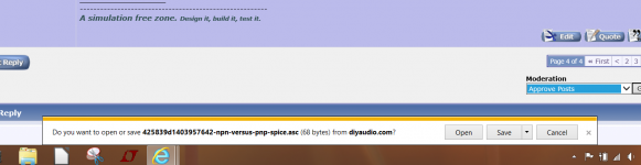
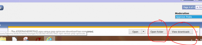
Try this and note all your steps. Here is a file called "Spice" which is just a blank .asc file. Download it and try and note any dialogue boxes that ask you or show you where the file is being saved.
Attachments
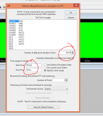
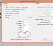
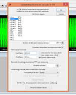
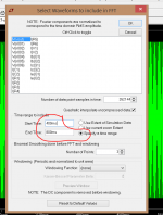
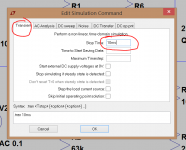
Settings for 80ms FFT
Ok ! for 20kHz i get the same graph.
But i am also interested in the 1kHz test ...
But for a test signal of 1kHz ... which settings for:
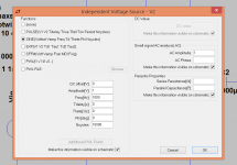
- Independent Voltage Source V2 and
- Select Waveforms to include in FFT
would you use ?
Thanks, gino
Lets try again, one of the pictures was wrong.
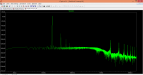
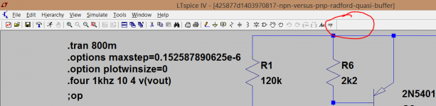
1kHz FFT and v2 settings. For the select FFT waveforms you are really only interested in Vout (which we labelled as such), but you can probe other points too. Here I have labelled the input as Vin and this is the FFT of the source.
Notice the .tran setting is now 800ms
1kHz FFT and v2 settings. For the select FFT waveforms you are really only interested in Vout (which we labelled as such), but you can probe other points too. Here I have labelled the input as Vin and this is the FFT of the source.
Notice the .tran setting is now 800ms
Attachments

Hi and thank you so much for your valuable support
First conditions of test
V2 = 0.1 V
R2 = 63k ; R5 = 5k
Result in the picture
The peaks still do not look very nice ... but the distortion is nothing
In end for me it is important to measure the distortion taking into account power amp sensitivity and input resistance
I set only 0.1 V because 0.5V give max power and load is 5k as i said before
The day that power amps will have same sensitivity and impedance by law that would be a nice day ... 😀
I guess i can be satisfied with this low distortion 😱
Thanks a lot again. Kind regards, gino 🙂
P.S. i am noticing that even a buffer is too much for this bloody amp ! why such a high sensibility ????
Line preamp have no problem to put out some Volts clean and with low distortion
I think that a good value for a power amp could around 4-5V ... and possibility at least 10K
It should not be that difficult ... for me of course, but for an audio designer ...
Attachments
Last edited:
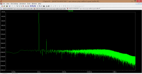
A Radford quasi buffer ... with no 3rd harmonic to speak of
And able to drive properly also a 5k load ... increasing the load performance gets better
Sounds like you are having fun 🙂
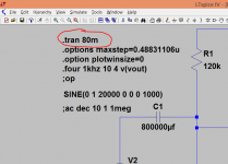
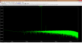
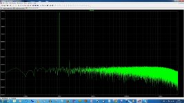
OK, this is your new circuit simulated at 1kHz, the second picture is running the sim for even longer.
You need to understand how the FFT works... when you run the FFT there is an option to select the number of sample points. It defaults to 262144. Look at the "maxstep" setting on the circuit. I tend to copy and paste all the commands into the simulation which makes it quick and easy but lets do it properly now 🙂
Here goes 😀
To get the sample points to align correctly you should take the "number of sample points" setting, so that's 262144 by default, and divide that into the time the FFT is going to run.
So... if you set your sim to run for 800ms (so .tran800m on the sim) and in the FFT window select it to run for 400ms to 800ms (so it looks at the last 400ms of the run) then we have 400ms divided by 262144 which is 0.4/262144 which is 1.52587890625e-6
That figure becomes the timestep and is entered onto the simulation. And here is the result......
Attachments

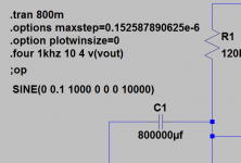
This is how you enter commands. As mentioned, I tend to copy and paste a whole block into a circuit but you can enter them all individually too.
I have renamed your circuit "Test Circuit" and attached it here. Download it and have a look. I've removed the commands, which you can add one by one.
Look at the "op" icon on the top row. That allows you to enter or modify commands.
First thing you want to do is run the DC part of the simulation. So go into "edit simulation" by right clicking the circuit and selecting the "DC op pnt" tab and click OK. As you move your cursor you will find it drags an empty box with it. Just drop the box onto a blank area (anywhere) on the diagram and it will change to .op
That means you can run the simulation for DC conditions.
Now we add the AC part of the simulation so click "edit simulation" again and this time select "transient". Depending on your chosen test frequency, you now enter a value for "stop time". If you have chosen 1kHz as the test frequency then that means each cycle lasts 1ms. So to see ten cycles on the screen you need to set the stop time at 10ms (as in the diagram). Click OK and you get another box to drag and drop on the diagram. This is the .tran part of the command. That is now the active feature and running the sim will display the 10 cycles.
(you can drop the commands anywhere on the diagram and move them with the "hand" icon to neaten things up.
Attachments
Not IE, windows explorer to search for files that are on my HDD.Are you using IE or something else ?
Try this and note all your steps. Here is a file called "Spice" which is just a blank .asc file. Download it and try and note any dialogue boxes that ask you or show you where the file is being saved.
I have the .asc and am working my way through the LT instructions.
Not IE, windows explorer to search for files that are on my HDD.
I have the .asc and am working my way through the LT instructions.
OK.
I find it more convenient to save all files to a folder in documents rather than the program files which LT does by default.
And for ginetto too... its worth occasionally searching your PC for .raw files. If you've set LT to delete these automatically then it will, but itcan catch you out if you rename a file and save it while the simulation is open. Then the temp files don't get deleted and they can be pretty big. Even this simple circuit generates 20mb or so temp .raw files.
Sounds like you are having fun 🙂
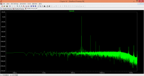
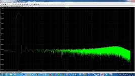
Hello ! very very much and finally .... look at the FFT 😀
I have set:
Stop time = 80ms
and in the FFT
Start time =40ms and End Time = 80ms
I told you that i am slow, very slow ... 😱
And the result is attached ! finally !!!! Thank you very much for your patience 🙂
Speaking of the circuit is impressive how there is only a little bit of 2nd order distortion ... is not amazing ?
I have also decreased the gain at almost 1 and the V1 = 30V
I should find some nice kit for this voltage ... the high voltages are much less common but 30V is common ... i could even use a +/-15V dual supply i guess
I think i will try the buffer.
Thank you very much indeed
Kind regards, gino 🙂
P.S. better to get a tattoo with these values 😀
Attachments
Last edited:
I'm stuck at posts 56 & 57.
I get 73.xx% distortion when I look at the error log.
And the FFT starts at 1kHz.
same problem as Ginetto @ post57
by post63 solved !
How solved?
I get 73.xx% distortion when I look at the error log.
And the FFT starts at 1kHz.
same problem as Ginetto @ post57
by post63 solved !
How solved?
- Status
- Not open for further replies.
- Home
- Member Areas
- The Lounge
- NPN versus PNP