Bob Cordells "Designing Audio Power Amplifiers" covers it all 🙂
Its feeding time here too... I'll be back shortly. See if you can change the transistors to something else 😀 and alter resistors.
Its feeding time here too... I'll be back shortly. See if you can change the transistors to something else 😀 and alter resistors.
Bob Cordells "Designing Audio Power Amplifiers" covers it all 🙂
Its feeding time here too... I'll be back shortly. See if you can change the transistors to something else 😀 and alter resistors.
Hello again ! Bought ! Thank you ! 😀
I hope i will learn something ... 😱
There is a lot of math and i am not very good at that, unfortunately
The ability with math is really a gift.
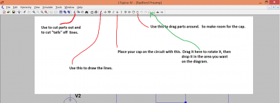
Have a try at making your circuit look like this modified one.
You can save the altered version under a new name (file > save as, top left)
Yes ! this is the idea ... actually what i would like to do also is:
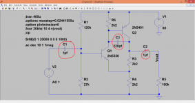
1) change the freq from 20 to 1 kHz
2) change the Vin to some 0.1-0.2 V
Let's see if i am able to do at least this by myself 🙄
Kind regards, gino
Hello 🙂
I tried to modify the original file and i am attaching the result
Problems:
1) i cannot delete the question marks on the right side
2) i have set AC in = 0.2 V but it shows 0.1 (?)
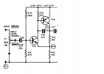
3) the original radford schema has a small 47pF cap (C26) placed between Q1 and Q2 i read for stability issues. Can we do without it ?
I have run the simulation and the spectrum looks fantastic 😱
Can you confirm this ?
I am going to build this 🙄
Thank you so much again, gino
I tried to modify the original file and i am attaching the result
Problems:
1) i cannot delete the question marks on the right side
2) i have set AC in = 0.2 V but it shows 0.1 (?)
3) the original radford schema has a small 47pF cap (C26) placed between Q1 and Q2 i read for stability issues. Can we do without it ?
I have run the simulation and the spectrum looks fantastic 😱
Can you confirm this ?
I am going to build this 🙄
Thank you so much again, gino
Attachments
Use the scissors (on the top toolbar) to cut the ??? out.
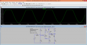
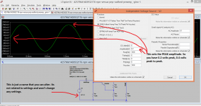
The input voltage works like in the picture here.
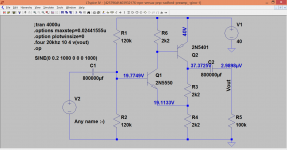
If you set the "edit simulation" back to "DC op pnt" you can click anywhere on the circuit and attach the voltages present as in second picture. Now when you change any values, the new voltages will appear automatically.
So... your circuit has a problem 😀 Look at the collector voltage of the PNP. Set the input voltage to 2 volts and run the "transient" simulation again. It clips. I think you altered the bias resistors (120k ?). So you need to tweak that 120k right back down. Keep increasing the input voltage and get it to clip symmetrically.
And this is easy to do... frequency response. Last picture is back to my circuit and with 1uf caps.
The input voltage works like in the picture here.
If you set the "edit simulation" back to "DC op pnt" you can click anywhere on the circuit and attach the voltages present as in second picture. Now when you change any values, the new voltages will appear automatically.
So... your circuit has a problem 😀 Look at the collector voltage of the PNP. Set the input voltage to 2 volts and run the "transient" simulation again. It clips. I think you altered the bias resistors (120k ?). So you need to tweak that 120k right back down. Keep increasing the input voltage and get it to clip symmetrically.
And this is easy to do... frequency response. Last picture is back to my circuit and with 1uf caps.
Attachments
Use the scissors (on the top toolbar) to cut the ??? out.
The input voltage works like in the picture here.
If you set the "edit simulation" back to "DC op pnt" you can click anywhere on the circuit and attach the voltages present as in second picture.
Now when you change any values, the new voltages will appear automatically.
So... your circuit has a problem 😀 Look at the collector voltage of the PNP. Set the input voltage to 2 volts and run the "transient" simulation again. It clips
Thanks a lot. I see. 😱
Which would be then a good value for voltage at PNP collector ? just to have a reference 😕
I think you altered the bias resistors (120k ?). So you need to tweak that 120k right back down.
Keep increasing the input voltage and get it to clip symmetrically.
And this is easy to do... frequency response. Last picture is back to my circuit and with 1uf caps
Yes you are right. I did that.
I will do as you say. I have changed R2 to 47k now.
The distortion spectrum is even better !!! 😕😱🙄
In general to decrease distortion in which direction i have to go ? 😕😕
Because i am playing with components but i have no idea what changes to try
And can you confirm that this circuit is low in distortion ?
It could be a good line preamp ?
Thanks a lot again, gino
Attachments
Last edited:
Give me 5 minutes and I'll see what I can do with your circuit 🙂
There is a bit more about distortion settings in LT that you need to understand.
There is a bit more about distortion settings in LT that you need to understand.
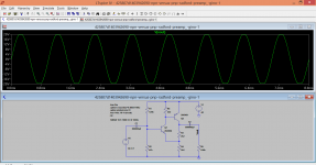
OK, with 47k the clipping is good.
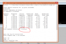
Distortion... 🙂
FFT... 🙂
How about a squarewave test 😀
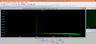
These are at 1kHz (look at the "commands" on the diagram. Do you see the timestep settings are different and that it says .four 1kHz instead of .four 20kHz. You need different settings for the two frequencies.)
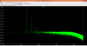
Distortion... 🙂
FFT... 🙂
How about a squarewave test 😀
These are at 1kHz (look at the "commands" on the diagram. Do you see the timestep settings are different and that it says .four 1kHz instead of .four 20kHz. You need different settings for the two frequencies.)
Attachments
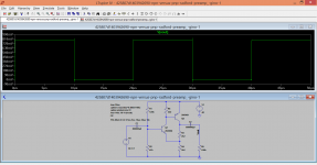
And squarewave. Look at the settings. 20us period and 10us "on time". So its a 50:50 duty cycle. The setting in the transient tab of the sim is altered to say 100us to show 5 complete cycles.
The second picture has the cap added for hf roll off... and that is the better option for a real build. Maybe not quite so large but it should be present really.
Back later 🙂
The second picture has the cap added for hf roll off... and that is the better option for a real build. Maybe not quite so large but it should be present really.
Back later 🙂
Attachments


OK, with 47k the clipping is good.
Good ! of course this circuit is supposed to work as a line stage
Maybe with 1 or 2V i will have the max power at the power amp outs
Well within the clipping of the circuit i guess
Distortion... 🙂
FFT... 🙂
These are at 1kHz (look at the "commands" on the diagram. Do you see the timestep settings are different and that it says .four 1kHz instead of .four 20kHz. You need different settings for the two frequencies.)
Well this looks much better ! how did you do that ?
Nice spectrum, isn't it ?
How about a squarewave test 😀
Well that next week 😀
I have so much stuff to study already ... i have to digest this before
Thanks a lot again, gino
And squarewave. Look at the settings. 20us period and 10us "on time". So its a 50:50 duty cycle.
The setting in the transient tab of the sim is altered to say 100us to show 5 complete cycles.
The second picture has the cap added for hf roll off... and that is the better option for a real build. Maybe not quite so large but it should be present really.
Back later 🙂
Thanks a lot again. In the original there is a 47 pF that could do fine.
I have a general question. Do you think that commercial designs for line preamps perform much better than this ?
It seems to me quite good already.
What is your opinion ? honestly 🙂
Thanks a lot again, gino
P.S- sorry last one ... how did you get this very nice graph ? with which settings ? if you tell me i will not touch anything for all the year ... it is just splendid !

Last edited:
I turned up late for my LT lessons.
Six of the belt for me.
And now lot's of homework to catch up.
Thanks Mooly.
Six of the belt for me.
And now lot's of homework to catch up.
Thanks Mooly.
I saved the Radford,,,asc file.
I can't find it.
How does Win7 search work?
I have tried opening windows explorer and entered *.asc as the search and no results came up.
I clicked on the Start icon and entered *.asc and "No items match your search" came up
I changed to asc and still "No items match your search" came up.
At the bottom "see more results" shows, click and the search screen just disappears.
How do I find ALL the .asc files? There should be hundreds of them.
Does the "*" wild-card still work?
Has it gone in your downloads folder ?
(I'm trialling W8.1 Enterpise so can't just try exact W7 keyclicks to check)
(I'm trialling W8.1 Enterpise so can't just try exact W7 keyclicks to check)
Good ! of course this circuit is supposed to work as a line stage
Maybe with 1 or 2V i will have the max power at the power amp outs
Well within the clipping of the circuit i guess
Well this looks much better ! how did you do that ?
Nice spectrum, isn't it ?
Well that next week 😀
I have so much stuff to study already ... i have to digest this before
Thanks a lot again, gino
You'll never come to close to clipping on a 40 volt rail and with low gain. Try reducing the supply voltage and altering the bias to suit.
Thanks a lot again. In the original there is a 47 pF that could do fine.
I have a general question. Do you think that commercial designs for line preamps perform much better than this ?
It seems to me quite good already.
What is your opinion ? honestly 🙂
Thanks a lot again, gino
P.S- sorry last one ... how did you get this very nice graph ? with which settings ? if you tell me i will not touch anything for all the year ... it is just splendid !
It's good, sonically very very good indeed. Its limitations are limited drive ability. Try reducing the load resistor to say 600 ohms (which most audio opamps are rated for) and see what happens to the max available voltage swing and also how the distortion alters.
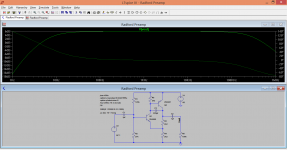
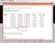
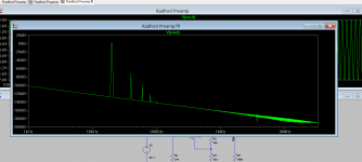
To get good simulation results you need to run the simulation for long enough. That's the "tran xxx" setting. 400us gives just 8 complete cycles. 4000us gives ten times as many (make sure you have enough cycles set up in the source voltage to cover the time the sim runs).
Look at the settings here. I altered it to run over 3ms to 4ms (so its looking at the last 25% of the run). The slope on this FFT is caused by having the caps at 1uf, so they are confusing the result as the circuit stabilises. Making the caps massive removes that problem, they are so large that nothing materially changes during the brief simulation run.
Attachments
You'll never come to close to clipping on a 40 volt rail and with low gain.
Try reducing the supply voltage and altering the bias to suit.
Fine ! yes i do not think i will need more than 2V
It's good, sonically very very good indeed. Its limitations are limited drive ability.
even with a 5K load ? i have an amp that i like with such low impedance unfortunately ... could i have problems ?
Try reducing the load resistor to say 600 ohms (which most audio opamps are rated for) and see what happens to the max available voltage swing and also how the distortion alters
I guess you are referring to R4 ? or R3 ?
To get good simulation results you need to run the simulation for long enough. That's the "tran xxx" setting.
400us gives just 8 complete cycles. 4000us gives ten times as many (make sure you have enough cycles set up in the source voltage to cover the time the sim runs).
Look at the settings here. I altered it to run over 3ms to 4ms (so its looking at the last 25% of the run). The slope on this FFT is caused by having the caps at 1uf, so they are confusing the result as the circuit stabilises. Making the caps massive removes that problem, they are so large that nothing materially changes during the brief simulation run
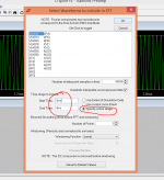
I tried ... not working with the followin settings in the window
Edit Simulation Command
Stop Time = 4000u
Select waveforms to include in the FFT
Start Time = 3ms
Stop Time = 4 ms
Number of data point samples in time = 65536
I think i have a problem with the X axis because the graph starts from 1kHz ...
Thanks, gino
Last edited:
ascAnd its dot (as in full stop) asc. Just try that, it should show the files.
.asc
*.asc
all show no results.
My downloads goes to blank when I shut down the browser.
I downloaded the asc and used it to follow your instructions. I saved it when still in LTspice.
But it's not in the LTspice folders: examples, educational, jigs, etc.
How do I search My documents?
- Status
- Not open for further replies.
- Home
- Member Areas
- The Lounge
- NPN versus PNP