That's the one. I built the Radford many many years ago, the preamp was excellent.
The ratio of R33 and R34 set the gain and altering these would need a tweak of the base bias network to keep the output point at an optimum value for symmetrical clipping. R32 helps with the hf performance and allows quick turn off of the PNP device. Its pretty non critical in absolute terms.
That's an easy stage to simulate 🙂
That's the one.
I built the Radford many many years ago, the preamp was excellent.
Thank you very much indeed for confirming all the rumors
I think that without the "unnecessary" tone controls and output stage it could sound even better.
Every stage acts like adding distortion i guess
But of course layout, parts selection and the quality of the PS are decisive for sound.
Still i have to start from somewhere.
Line stages are the most interesting thing for me.
I would like to find a good one and keep it for long time.
The ratio of R33 and R34 set the gain
No problem at all for the gain ... even a unity gain buffer could be enough
But gain of 2 will be just perfect.
and altering these would need a tweak of the base bias network to keep the output point at an optimum value for symmetrical clipping
What do you think it could be a good value for TS7 bias ?
In the original is around 7 mA. Should i keep it this way ?
Or maybe higher is better ?
R32 helps with the hf performance and allows quick turn off of the PNP device. Its pretty non critical in absolute terms.
That's an easy stage to simulate 🙂
I start from the assumption that is a good design
I understand that the higher the Vsupply the lower the distortion.
So i would be tempted to go even higher ... like 80V 😱
So it will be up to me not to ruin it with bad layout and so on.
I am going to use very overrated parts ... very.
To avoid the need of heatsinks.
Just the bare bjts.
Thanks again, gino
80 volts is a bit much tbh for a line stage. If the source is digital (say CD at around 2 volts RMS) and you only want a gain of 2 then 80 volts is way to high.
Where is the 7 ma coming from ? The quiescent current in TS7 will only be around 300 to 500uA at the most.
Where is the 7 ma coming from ? The quiescent current in TS7 will only be around 300 to 500uA at the most.
80 volts is a bit much tbh for a line stage.
If the source is digital (say CD at around 2 volts RMS) and you only want a gain of 2 then 80 volts is way to high
Hi and thanks again and please me explain
A really nice guy here has simulated this very circuit for me
Initially, i was not clear, he simulated with a Vsupply= 36V with very good distortion results.
Then i mentioned that the original Vsupply was 60V from the schema.
He risimulated the all thing with even better result ... almost no distortion from 3rd order up 😱
You can now understand that for me i would use very very high Vsupply
In general i do not understand why for tubes nobody complain for very high voltages ... instead for solid state the usual +/- 15V .... or so to speak
I would use a bjt in its optimal working conditions if i only i knew how to calculate them.
Where is the 7 ma coming from ? The quiescent current in TS7 will only be around 300 to 500uA at the most
Sorry ... i was thinking that the Ibias in the TS7 was the same current flowing through R34 ... was i wrong ?
This is a very important point to understand which kind of bjt i could use.
I have bought these two here ... just to avoid any need of heathsinks even with high Vce and I bias
NPN 2sc2238B
PNP 2sa1695
Maybe i have exaggerate a little ... but i want absolutely avoid the need of heatsinks ... i hate them
Bare chips
Thanks again, gino
Well, valves generally do operate at higher voltage but its a whole different ball game though with valves being "voltage" driven rather than "current" driven like bjts. They don't have current gain in the same sense that transistors do.
Your two transistor circuit will perform well with any generic devices... and the trouble with simulation is that its easy to chase numbers... with the reality being that the real version will probably have much higher distortion (although still very low in absolute terms). Distortion will be affected by loading too.
I'd probably run such a stage on 30 to 40 volts.
The current in TS7 depends on the actual gain of the two transistors used. If the PNP is low gain then more base current needs to be pulled from it, and that flows in TS7.
If you use LTSpice I can post a file and then you can try it yourself 🙂
Well, valves generally do operate at higher voltage but its a whole different ball game though with valves being "voltage" driven rather than "current" driven like bjts.
They don't have current gain in the same sense that transistors do.
Hi and thanks again. I do not like valves .. well the problem is that i do not like their bass ,,, is always soft ... not very solid
And with preamp and amp ... instead the midrange is very ok.
Your two transistor circuit will perform well with any generic devices... and the trouble with simulation is that its easy to chase numbers... with the reality being that the real version will probably have much higher distortion (although still very low in absolute terms).
Distortion will be affected by loading too.
I understand that one thing are the models and another the real components
For instance the model is based on average characteristics i guess
So the software can tell mostly in which direction to go to get better results ?
I have found a kit for the PS based on the tl783 that can go very highI'd probably run such a stage on 30 to 40 volts
Almost 100 V ,,,, so i would like to stay on the original 60V
But also avoid completely any need of heatsink selecting more robust parts
I have bought some 2sc2238B and 2sa1695
The current in TS7 depends on the actual gain of the two transistors used.
If the PNP is low gain then more base current needs to be pulled from it, and that flows in TS7.
If you use LTSpice I can post a file and then you can try it yourself 🙂
I would love to be able to use LTSpice but someone told me that Multisim is more user friendly and i need something very very easy to use
Actually i tried to download the student edition and i am not a student
So i do not know how to proceed ... i have no university to name.
It is very difficult even the download ... 😱
In the end i think i will stick with the original values for resistors
Thanks anyway for your kind help
Kind regards, gino
Last edited:
Hi i have downloaded LTSpice 
In the weekend i will look for some tutorial on youtube just to make some practice with the basic commands 🙄
Thanks a lot for the kind and valuable suggestion.
Kind regards, gino 🙂
In the weekend i will look for some tutorial on youtube just to make some practice with the basic commands 🙄
Thanks a lot for the kind and valuable suggestion.
Kind regards, gino 🙂
If you want to try LTspice 🙂 then I'll tell you how to run the file and set it up. You'll be up and running in no time. The programme installs in a couple of minutes. Up to you... no pressure 😀
Linear Technology - Design Simulation and Device Models
Simulation is really good for seeing how changes made to a design affect its performance... as you say... seeing which way its heading.
Linear Technology - Design Simulation and Device Models
Simulation is really good for seeing how changes made to a design affect its performance... as you say... seeing which way its heading.
If you want to try LTspice then I'll tell you how to run the file and set it up. You'll be up and running in no time.
The programme installs in a couple of minutes. Up to you... no pressure
Linear Technology - Design Simulation and Device Models
Hi and thank you so much for your very kind support ! 😀
Yes i have installed the program, but i need a little time because i saw some tutorial on youtube 😱
I will come back after some study of the basic functions ... never seen a sim SW before 😱
Simulation is really good for seeing how changes made to a design affect its performance... as you say... seeing which way its heading.
Posted together.
Yes ! this is exactly my idea ... to try to change some values and see for the results
Of course only the scope on a prototype will tell the truth ... but the direction also the sim SW can tell if it is the right one or not i guess
Do you want a file to play with now, to run and see what it does ?
Yes please but i will need anyway the weekend to realize something ...
I am a little confused on how to use it
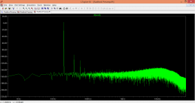
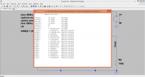
Here is the Radford preamp distortion spectrum with a 20kHz fundamental test tone
Am i wrong or it looks particularly good ?
I have seen much worse in some high end preamps 😉
Ok they were real pieces ... maybe the real difficulty is to build a unit that approaches the sim results ?
The nice thing here is that the gain is not so high ... is not a phono preamp i mean. That would be very difficult i think
I will try in the weekend to learn the basic commands
Then i will ask you about this .. FFT is called ? i love this graphs
It looks very nice ... what do you think ?
Thanks a lot again
Kind regards, gino
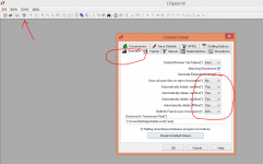
OK... first thing is to set it up so you know where its storing stuff and what its doing with files. Look at the first picture and set yours up the same. This sets it to delete files every time LTspice is closed.
I've attached the file for the Radford. For now, just download it and put it somewhere like "documents" or leave it in your downloads folder.
To run the file you can either (and this to some extent depends on your PC and its permissions) just click the file and that should open LT. So try that. If it gives an error or objects then open LT from its icon, right click the empty workspace and click "open" and browse for the file manually.
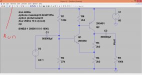
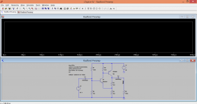
Doing either of those two operations should make it look like this (second picture).
Now either click "run" (the little man fourth symbol in along the top row) or just right click a blank area on the screen and select run.
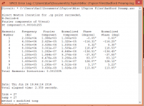
You should see this (third picture). Close the box that appears. Now over your cursor over any nodes in the circuit. You will see the DC values. Go on the transistor leads and see the currents, and the transistor dissipation.
Yes 🙂
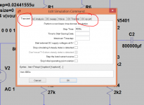
When you are happy with that, right click the circuit (a blank space) and select "edit simulation". You will see a box appear. The setting at the moment is "DC op pnt" that runs the sim to show the DC conditions. Change it to transient and click OK. (Fourth pic)
Now run the sim again and you should see this (fifth pic). If you place the cursor over the output (where I've marked Vout) and left click then you should see the output waveform. You can go on any part of the circuit and probe the AC currents and voltage. Try it.
That's probably enough to be going on with for now 🙂
The file is attached at the bottom, the .asc
I've attached the file for the Radford. For now, just download it and put it somewhere like "documents" or leave it in your downloads folder.
To run the file you can either (and this to some extent depends on your PC and its permissions) just click the file and that should open LT. So try that. If it gives an error or objects then open LT from its icon, right click the empty workspace and click "open" and browse for the file manually.
Doing either of those two operations should make it look like this (second picture).
Now either click "run" (the little man fourth symbol in along the top row) or just right click a blank area on the screen and select run.
You should see this (third picture). Close the box that appears. Now over your cursor over any nodes in the circuit. You will see the DC values. Go on the transistor leads and see the currents, and the transistor dissipation.
Yes 🙂
When you are happy with that, right click the circuit (a blank space) and select "edit simulation". You will see a box appear. The setting at the moment is "DC op pnt" that runs the sim to show the DC conditions. Change it to transient and click OK. (Fourth pic)
Now run the sim again and you should see this (fifth pic). If you place the cursor over the output (where I've marked Vout) and left click then you should see the output waveform. You can go on any part of the circuit and probe the AC currents and voltage. Try it.
That's probably enough to be going on with for now 🙂
The file is attached at the bottom, the .asc
Attachments
Hi ! i did it !!!! It works !!! Thanks a lot indeed !
I see a sinusoid that goes from -2 to +2 V !
I guess the gain of the circuit is 2 so it means that the input signal is 1 Vac ?
Great ! i do not know how to save the display as a picture but it is nice
In order to get a distortion spectrum ... is it very difficult ?
How can i see/change V2 ? in amplitude and freq ?
I would like to use a lower V for signal and the usual 1 kHz
I think that in the end distortion simulations are the most used function i guess
This is my very goal ... is it difficult ?
Thanks a lot again
Kind regards, gino
Another thing ,,, i cannot see the transistor dissipation
This is also very important i guess to select the suitable one
Thanks again, gino
This is also very important i guess to select the suitable one
Thanks again, gino
🙂
One step at a time. Run the file again (so you see the sine) and hover cursor over the collector of the transistor. The cursor will show the dissipation.
One step at a time. Run the file again (so you see the sine) and hover cursor over the collector of the transistor. The cursor will show the dissipation.
🙂
One step at a time. Run the file again (so you see the sine) and hover cursor over the collector of the transistor. The cursor will show the dissipation.
The actual dissipation figure is shown bottom left in text. Try it over resistors too.
... hover cursor over the collector of the transistor ...
 😀 Yessss !!!! sorry in the excitement i lost some words !
I can see now ! 174 mW on Q2 collector !
You know what .... i think i exaggerated a little 😱
I bought a 150W PNP 😀
that should work fine also without heatsink i guess 🙄
Anyway ... i see a strange value for C1 and C2 ... how is that ???
Thank you sincerely again, gino
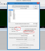
To see the FFT we have to consider a couple of things. On AC coupled circuits the time constants of the coupling caps interfere with the FTT so one approach is to make those very very large (as I have done). The second thing is to run the simulation for long enough so that a good result is obtained.
So try this.
1/ Right click the workspace and select "edit simulation CMD"
2/ On the transient tab do you see where it says 400u (400 microseconds). That's the time scale of the X axis. Change that to 4000u and click OK
3/ Run the simulation again. Do you see what has changed. It runs for ten times as long.
4/ To see the FFT look at the waveform on Vout as before.
5/ Move the cursor anywhere in the "sine wave screen" and right click.
6/ Go to the bottom of the menu that appears and go to where it says "view". A flyout menu will say FFT. Click that.
7/ Set it up as shown here and and click OK.
Attachments
Good 'innit 😀
Try the FFT. If you get stuck I'll put pictures up... see how you go on with that.
😱😱😱😱
It is gorgeus !!!!! can i save the FFT as a picture ?
I want to show it to my friends 😉
They say that i am a chat only guy 😱
Thank you sincerely again.
I wonder if there is a book explaining all these settings ... especially for FFT of course
Please excuse me but i have to leave now because is dinner time now here (Norway)
I will try to make some changes myself in parts values and see 🙄
Thanks a lot again for now.
Kindest regards, gino
- Status
- Not open for further replies.
- Home
- Member Areas
- The Lounge
- NPN versus PNP