I've always considered this the bicycle approach to loudspeaker improvement. A bicycle is a fairly standardized design with geometry and parts definitions all worked out. You don't design one totally different than the ones that came before. But there are many levels of of component quality so you can always improve a bike by replacing parts of one quality level with a higer level.
Some assume the same applies to speakers. If I replace all the wire with "better" wire...If I replace all the capacitors with "better" capacitors....Just like new brakes and deraileurs, I can elevate the speaker from mediocre to good.
Well it doesn't work that way. Give me mundane components and superior design any day. But then when I measure and listen to a speaker I usually find significant flaws that I would want to improve (flaws not fixed by better wire!).
Capacitor sound quality? This is a basic tenant of the religion of audiophilia. As such nobody will dissuade anyone else through the logic of their arguements. You believe it or you don't.
Little bits with two wires and an impedance that halves every Octave. Thats all they are. The simplest model of a practical capacitor includes a high value resistor in parallel (leakage) and a small value in series (ESR). These elements can be significant enough to have a small impact on frequency response, but that is compensated for in the tuning process. ESR too high? Reduce the padding resistor. They aren't quality effects they are just differrences. No "the dark between the notes" effect here.
Now, the more sophisticated the proponent the more sophisticated the argument. I personally like the dielectric absorption arguement. It sounds really high tech and lofty. Nevermind that it is still a linear effect and that we can't measure any distortion in our speakers from it (the gross amounts of transducer distortion would certainly get in the way). I don't think we could measure THD in a test fixture from it?
It has to be a reason why every capacitor has its individual sonic signature.
Resonances in crossover components? I've never measured any but there might be some somewhere. Laminated core transformers would be a place to look. How would they compare to the gross cabinet resonances? And even cabinet resonances have a threshold of audibility. We think capacitors are worse offenders?
The "double blind test" cry does get tiresome after a while but it is the only answer. If these effects are real then anyone should be able to pick out offending components without foreknowledge of what they are listening to. This is fully accepted in other fields. You can't do drug testing or even proper wine tasting when you can "see the label". Placebo effect is well documented and certainly applies to audio.
But again, nobody is going to convince anyone to change their view, anymore than I can convince a Republican to vote Democratic or vice versa. We believe what we believe.
David
I'd drawn a similar conclusion about capacitor ESR. It's a linear sort of effect and not worth worrying about. ")
I often wonder if the rewiring experiments with new components ("Night and Day, mate!") is just down to fresh metal on the speaker clips. It's interesting to short out a bass with, say, a screwdriver and push it. You get a lot of mushy noise from it if the connection is iffy!
The high end Duelund/Tannoy experiment had one possibly important factor. The crossover was taken outside the cabinet and not prone to feeling vibration from the drivers. That's a simple fix to any microphone effects really, and doesn't depend on boutique components. We might try hot glue on components too for a bit of damping.
The darkness word really just describes a lack of distortion and overhang in a speaker. Good signal to noise ratio, in other words. Mush can come from cabinets, poor contacts and chassis basket ringing amongst other things.
And why it is necessary to "undo" and redo repeatedly to find out which is apparently better/different..............I often wonder if the rewiring experiments with new components ("Night and Day, mate!") is just down to fresh metal on the speaker clips. It's interesting to short out a bass with, say, a screwdriver and push it. .............
Edit:
I typed dufferent
maybe I should have left it like that?
I'd drawn a similar conclusion about capacitor ESR. It's a linear sort of effect and not worth worrying about.
........
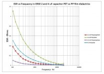
ESR (ohms) vs freq. is not linear as shown in the chart I provided in the downloadable pdf file at this link. Effect of Film dielectric type on capacitor ESR
ESR (ohms) vs freq. is not linear as shown in the chart I provided in the downloadable pdf file at this link. Effect of Film dielectric type on capacitor ESR
That's interesting, Carl. Do you mind if I quote your findings?
I always use linear in the sense of Linear filters under fourier transform, and hence without intermodulation distortion. They don't necessarily have to be a straight line. A notch filter is still linear.
MKT Polyesters are generally used into high impedance in electronics, so are adequate there. Because they rarely come above 2.2uF, you'd end up paralleling them in most crossover applications. That must be down to using a thinnish metallised foil.
But certainly a consideration at low frequencies. Interesting.
Attachments
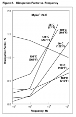
Ah wait. I could be completely wrong here, but I think the dissipation factor (DF as the tangent of the phase angle) behaves differently! It gets worse with higher frequency.
ESR is evidently a rather nebulous quantity with capacitors. But it makes a case for thicker metallised coatings. Manufacturers are not going to use any more material than they have to for a given application.
ESR is evidently a rather nebulous quantity with capacitors. But it makes a case for thicker metallised coatings. Manufacturers are not going to use any more material than they have to for a given application.
Attachments
That's interesting, Carl. Do you mind if I quote your findings?
No, I don't mind. I've always found the ESR differences with different film types when doing xover upgrades and making sure not to alter the transfer function significantly. IMO, that is a key determinatlor of voicing in the crossover region.
This popped up while I was searching my files for something totally unrelated!
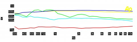
I test lots of different types of capacitors, this shows one of the worst. I never got to try SY's favorite loosely wound audophile specials.
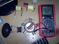
A DC voltage was applied to the D.U.T. through a resistor. 9V/10K if I recall correctly. They were then placed on a woofer turned into a shaker table.
While grabbing the image the legend seems to have gotten lost. So what is here is a Mylar cap and an aluminum elctrolytic, two samples mounted vertically and horizontally. Base line is a shorted test lead.
I test lots of different types of capacitors, this shows one of the worst. I never got to try SY's favorite loosely wound audophile specials.
A DC voltage was applied to the D.U.T. through a resistor. 9V/10K if I recall correctly. They were then placed on a woofer turned into a shaker table.
While grabbing the image the legend seems to have gotten lost. So what is here is a Mylar cap and an aluminum elctrolytic, two samples mounted vertically and horizontally. Base line is a shorted test lead.
Attachments
Last edited:
I really can't interpret your data there, Simon7000.
Personally I haven't found any smoking gun with capacitors yet, but I'm finding some interesting things with coils!
An inductance meter generates a substantial test tone around 1-2kHz. My little speaker with a 0.2mH coil in series nearby is whistling away quite happily here. You can hear it. It falls off rather quickly with distance and perpendicular alignment as you would expect. 2-3" should be enough to get this down to inaudible levels with the test tone I'm using.
The 1mH ferrite is also substantially affected by being placed on a metal plate. That's a 20% reduction in inductance. Makes a case for point to point wiring. I think Troels did some stuff like this.
FWIW, putting an open circuit ferrite coil within a 0.27mH coil increased the inductance 4 fold to around 1mH. Which is an interesting order of scale for permeability IMO, even if the OC coil might have influenced things a little.
I suppose the worst circuit for some magnetic interaction must be a tuned notch at the tweeter Fs frequency. To find microphonic effects, as with those ceramic layer capacitors, we need to apply a polarising voltage of course.
Attachments
Last edited:
I really can't interpret your data there, Simon7000.
That's the idea. There's a 34% probability that enough details will be pried out after a hundred posts or so that will cause people to forget what it was originally about.
A few comments by Troels, in a blind trial, that have got buried in one of his lesser-known (& now discontinued) projects: SEAS-W11CY001
Basically, couldn't hear much / any significant difference in a blind trial between two XOs, one constructed using relatively high end components (Mundorf Supreme caps, Tritec coils + Mox resistors), the other with substantially cheaper components (Monacor polyprop caps, coils & sand-cast resistors). Granted, it can be criticised. It's not under strict scientific conditions (better than sighted though), not a large sample size, multiple variables changed, it's a single speaker, & the size of the expensive components meant the XO board & component layout were altered. But he measured the filter behaviours as within 0.5dB of each other, suggesting not much impact there. Third version too with electrolytic caps too -even then, wasn't certain on differences, let alone improvements from one to another.
I'd tend to agree with his point re properly wound & baked coils. Certainly worth having.
Last edited:
That's a good point about baked coils. I suspect some of my Wilmslow aircoil ones on the plastic bobbins aren't.
I also tried a few things with capacitors connected to the speaker near a coil with the same test tone, and even an open circuit and short circuit film capacitor placed within a coil.
I couldn't hear anything from the speaker, or measure any change in inductance. Troels too found that only boutique caps in metal sleeves had a measureable effect. These are clearly behaving like a metal plate of low resistance, and hence have appreciable induced currents.
Placement of coils in crossover networks
Film caps seem insensitive to placement and stray magnetic fields.
Last edited:
Inductor Coil Crosstalk Basics | Audioholics
Placement of coils in crossover networks
Patent US4771466 - Multidriver loudspeaker apparatus with improved crossover filter circuits - Google Patents
This has pretty much been known for a long time now. The last link shows Richard Modafferi's patent for mutual coupling between inductors which he used in his JSE Infinite Slope Speakers.
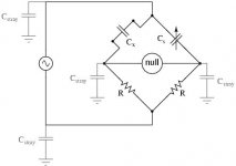
To make further progress, I think we need some sort of Bridge technique to test for microphonic effects with a DC offset, and look at some AC effects too.
It's simple enough, and quite old fashioned, but I don't have the gear to do this.
According to Clarity Cap, the cheap film caps are going to squeal at around 15kHz. Who knows?
It's simple enough, and quite old fashioned, but I don't have the gear to do this.
According to Clarity Cap, the cheap film caps are going to squeal at around 15kHz. Who knows?
Attachments
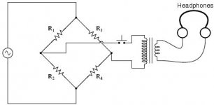
Is this the AC voltage across the capacitor DUT?
Yes
That's the idea. There's a 34% probability that enough details will be pried out after a hundred posts or so that will cause people to forget what it was originally about.
You could buy the article!
- Status
- This old topic is closed. If you want to reopen this topic, contact a moderator using the "Report Post" button.
- Home
- Loudspeakers
- Multi-Way
- Capacitor quality for crossover