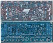
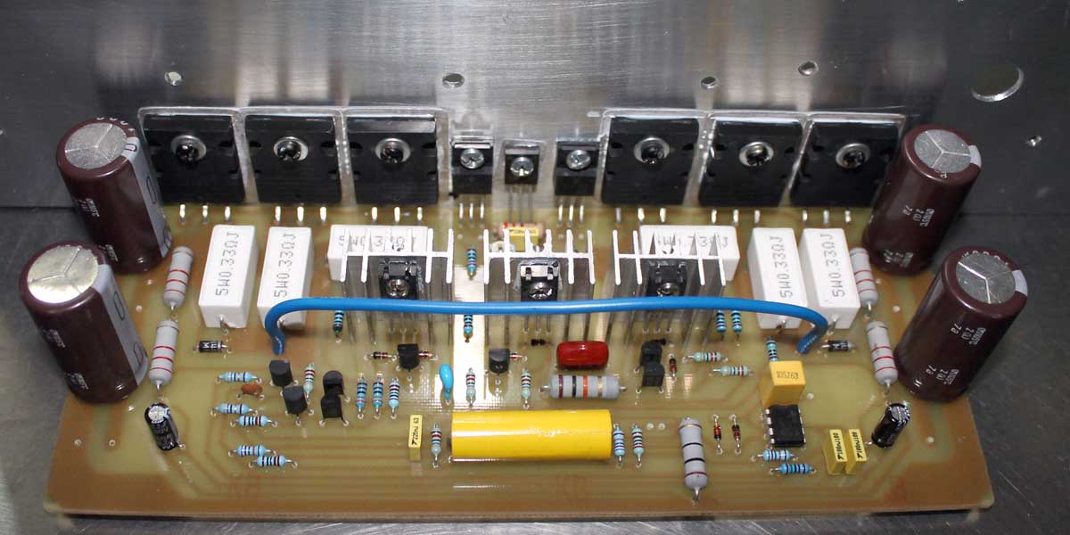
SR200 for 2014
So I decide to make a new one, please check this one out 😱
this one already tested, DC offset is 1.1mV with TL071, I have LF411 but I thought TL071 is good enough 🙂
If anyone want to convert it to pdf please PM me 🙂
I have the big jpg file 😀
Yes that a nice one, but when I ask for it & he is out of stock of that PCB... 😛Some nice pcb
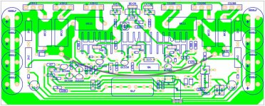
So I decide to make a new one, please check this one out 😱
An externally hosted image should be here but it was not working when we last tested it.
this one already tested, DC offset is 1.1mV with TL071, I have LF411 but I thought TL071 is good enough 🙂
If anyone want to convert it to pdf please PM me 🙂
I have the big jpg file 😀
Attachments

Last edited:
Yes that a nice one, but when I ask for it & he is out of stock of that PCB... 😛
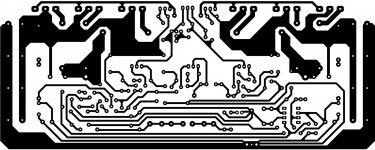
So I decide to make a new one, please check this one out 😱
An externally hosted image should be here but it was not working when we last tested it.
this one already tested, DC offset is 1.1mV with TL071, I have LF411 but I thought TL071 is good enough 🙂
If anyone want to convert it to pdf please PM me 🙂
I have the big jpg file 😀
Nice work, thanks for this pcb design.
Regards

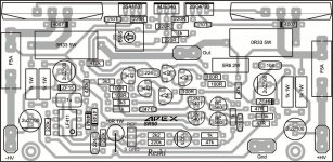
Hi Mr.Mile
can i build sr200 use pcb SR V3.1 NOT PCB SR V3.2??because in SR3.1 R18=1k and C7=470pF is removed from pcb.
The difference between SR v3.1 to SR V3.2.
View attachment 423589
R18=1k and C7=470pF can not be removed from pcb, C2=100pF also.
Last edited:
R18=1k and C7=470pF can not be removed from pcb, C2=100pF also.
what is the reason sir?
R18=1k and C7=470pF can not be removed from pcb, C2=100pF also.
thanks Mr.Mile,
I will complete all komponen.between the two schemes below which one do you recommend??


Pan,
add a variable resistor to that 18pF.
Tune the "output" with the VR and then replace with a fixed resistor once you have settled on the output stability that you require.
add a variable resistor to that 18pF.
Tune the "output" with the VR and then replace with a fixed resistor once you have settled on the output stability that you require.
Pan,
add a variable resistor to the C=18pF.
Tune the "output" with the VR and then replace with a fixed resistor once you have settled on the output stability that you require.
Hi Andrew T.
Is it the function of the C=18pF to adjust dc offset?and whether i should use osciloscop order to see the changes?
NO !
18pF is a stability compensation component.
You must measure the amp output to know what effect the 18pF is having.
You may have to change the 18pF if you have guessed at the wrong value.
It could be that 5pF to 10pF is more suitable.
The ONLY way to find out is to measure.
18pF is a stability compensation component.
You must measure the amp output to know what effect the 18pF is having.
You may have to change the 18pF if you have guessed at the wrong value.
It could be that 5pF to 10pF is more suitable.
The ONLY way to find out is to measure.
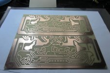
PDF SR200
Here the SR200 in pdf format for easier toner transfer 🙂
PCB size is 80 x 200 mm
the good news that this one don't need any aditional compensation 😎
Here the SR200 in pdf format for easier toner transfer 🙂
PCB size is 80 x 200 mm
the good news that this one don't need any aditional compensation 😎
Attachments
Last edited:
Here the SR200 in pdf format for easier toner transfer 🙂
PCB size is 80 x 200 mm
the good news that this one don't need any aditional compensation 😎
Thanks John Bali for sharing your layout design, i can't wait to try it
And also big thanks to Mr. Mile for the schematics
1N4007 reversed
I have found the 1N4007 is in reverse at my top silk so be carefull 😱
that the work one I build before I check all the top silk placement
Please forgive me...
Ok try it & please use it as reference :Thanks John Bali for sharing your layout design, i can't wait to try it
And also big thanks to Mr. Mile for the schematics
I have found the 1N4007 is in reverse at my top silk so be carefull 😱
that the work one I build before I check all the top silk placement
Please forgive me...
Send a message to moderator to delete wrong file then post again the right one.Ok try it & please use it as reference :
I have found the 1N4007 is in reverse at my top silk so be carefull 😱
that the work one I build before I check all the top silk placement
Please forgive me...
Nice work!
Obtain the many versions of the Studio Reference Amplifiers
I would like to obtain PCB's for the various Studio Reference Amplifers, i.e.
SR50,SR200,SR500,SR800,etc. If I had the Gerbers files I could send them
to a vendor to make the PCB's. Or does any of the PCB Software,i,e. Eagle,
Sprint,etc, convert PDF files into Gerber files? That would be great.🙂
Is anyone doing Group Buys on these PCB's? Let me know. Great Thread.😀
- Home
- Amplifiers
- Solid State
- Studio Reference Amplifier