Hello 🙂
I'm going to build a 2.1 amplifier in a few months, and I have a question about the two capacitor of the power supply. Due to size restrictions, its diameter should not exceed 18mm and the lead spacing should be 7.5mm.
It's going to be a 2*20W + 40W ( 8 ohms ) amplifier with a 14-0-14VAC 150VA toroidal transformer. I'm hesitating between two capacitors :
-> United Chemicon GPA 4700µF 35V - 4230mA ripple current ( http://www.mouser.com/ds/2/420/-273722.pdf )
-> Nichicon VK 6800µF 35V - 2800mA ripple current ( http://www.mouser.com/ds/2/293/e-vk-16658.pdf )
I read on the web that the capacitor will last longer with a bigger " ripple current capacity " for a given ripple current. However, I'm losing 2100µF with the United Chemicon GPA.
Which one would be the best ?
Both should be OK.
What bass performance are you expecting from your amplifiers?
6800uF and 4700uF are very low for extended and full sounding bass.
What bass performance are you expecting from your amplifiers?
6800uF and 4700uF are very low for extended and full sounding bass.
The subwoofer channel will be 40W. It's not very powerful so I'm not expecting ground shaking bass 🙂 In fact, I'm hesitating between lower capacitance but better ripple, and higher capacitance but worse ripple. I wish to optimize the bass performance.
Last edited:
Temperature is the most significant life-affecting factor. Ripple current is just a secondary correcting factor, and in an audio amplifier the capacitors are not subjected to a sustained ripple unless you listen all day long to 1KHz sinewave @ full power.I read on the web that the capacitor will last longer with a bigger " ripple current capacity " for a given ripple current. However, I'm losing 2100µF with the United Chemicon GPA.
The 6800µ is therefore a (very marginally) better choice.
Edit:
The above applies to class AB amplifiers but the situation would be different for class A
Last edited:
Thanks 🙂
I'm going to chose the Nichicon VK 6800µF 35V then. I wanted to put bigger capacitors but there is not enough space for them on the PCB
Thank you very much
I'm going to chose the Nichicon VK 6800µF 35V then. I wanted to put bigger capacitors but there is not enough space for them on the PCB
Thank you very much
Add 4 more before the PCB.
3pair of 6800uF gives the equivalent of +-20mF and 8.4A of ripple capability.
3pair of 6800uF gives the equivalent of +-20mF and 8.4A of ripple capability.
It sounds promising, but isn't it too much for a 2*20 + 40W 2.1 amp ? There will be two 3" satellites ( Tang Band W3-881SI ) and a 6.5" subwoofer ( Dayton DC160-8 ).
Too much? It is practically never too much unless you go into seriously insane values.It sounds promising, but isn't it too much for a 2*20 + 40W 2.1 amp ? There will be two 3" satellites ( Tang Band W3-881SI ) and a 6.5" subwoofer ( Dayton DC160-8 ).
6800µ will work perfectly though, but if you intend to listen to bass-rich contents at really high volumes, you will find they are a bit short. If you have room enough, it would be a good idea to double them. Going much higher would bring little or no benefit.
Maybe I could try doubling the capacitance by putting them in parallel. Two on one side and two on the other side of the PCB if they fit 🙂 I read it's better to keep them close to the chips.
My homemade 2.1 speaker system is currently running with a Logitech Z313 amplifier ( 2*5W + 15W ), with a switching power supply, a single 25V 4700µF capacitor from " Chang ", supplying a STA540 chip. It works pretty well, but power is of course limited, and the presence of cheap Samxon electrolytic capacitor ( 470µF 16V per output capacitor to filter the satellites ) makes the trebles harsh and not so detailed. If you want to see what is the actual Logitech quality for cheap speaker, a member on another forum has posted some photos here : Z313 Slideshow by Theaxethrow | Photobucket - This amplifier version is an " old " version, with still two stereo amplifier chips like my old X210, of which the Z313 is an evolution.
My homemade 2.1 speaker system is currently running with a Logitech Z313 amplifier ( 2*5W + 15W ), with a switching power supply, a single 25V 4700µF capacitor from " Chang ", supplying a STA540 chip. It works pretty well, but power is of course limited, and the presence of cheap Samxon electrolytic capacitor ( 470µF 16V per output capacitor to filter the satellites ) makes the trebles harsh and not so detailed. If you want to see what is the actual Logitech quality for cheap speaker, a member on another forum has posted some photos here : Z313 Slideshow by Theaxethrow | Photobucket - This amplifier version is an " old " version, with still two stereo amplifier chips like my old X210, of which the Z313 is an evolution.
Hello,
Something to read:
- http://www.diyaudio.com/forums/power-supplies/216409-power-supply-resevoir-size-169.html#post3320547
Something to read:
- http://www.diyaudio.com/forums/power-supplies/216409-power-supply-resevoir-size-169.html#post3320547
you misunderstand.Maybe I could try doubling the capacitance by putting them in parallel. Two on one side and two on the other side of the PCB if they fit 🙂 I read it's better to keep them close to the chips.
.............
The HF decoupling MUST be very close to the power pins of the device.
The MF decoupling can a slightly further away, because the higher inductance of the longer traces/wires does not interfere with the current passing to the HF decoupling and device.
The LF smoothing bank can be inches, or even feet, away and still work perfectly well.
No.the presence of cheap Samxon electrolytic capacitor ( 470µF 16V per output capacitor to filter the satellites ) makes the trebles harsh and not so detailed.
The harshness is almost certainly due to misplacement of MF and HF decoupling. Or maybe one or both has been omitted.
The smoothing capacitor does not need to be a "high quality" item. It just needs to be able to release it's charge in a smooth manner to suit the demand made by the speaker/s.
Last edited:
Thanks for your explanations. I'm going to think about it to properly do the decoupling job 🙂
Since the 2.1 board doesn't have MF and HF decoupling, I will have to put in parallel a ceramic 0.1µF capacitor and an electrolytic 100µF capacitor, and this to each Vcc and -Vee pin of each chip, all going to ground. I think I have to do the same for the 2 operational amplifiers. Well, it's going to be tough because the board is very small ... I'll be obliged to put all these decoupling capacitors on the other side of the PCB.
The ground is between the two power supply capacitors, and they are linked together by a wide copper area on the PCB. What if I remove some varnish from the PCB to directly solder the ground cable on it ? All the decoupling capacitors will be soldered on the same cable, which will be soldered directly on the ground. I wonder if it's a good idea
About the power supply capacitors, is an " Audio Grade " capacitor ( Nichicon Gold Tune, etc. ) better than a " General purpose " capacitor ? They are at the same price so I wonder.
Thanks for your valuable lessons 🙂
@ alayn91: Thanks, this topic is well explained
The decoupling capacitors should be connected to each other.
That connection is the Power Ground. The Output Zobel connects to this power Ground.
Then take one wire, or one trace, to the main smoothing capacitors.
That connection is the Power Ground. The Output Zobel connects to this power Ground.
Then take one wire, or one trace, to the main smoothing capacitors.
The MF decoupling is where capacitor parasitics and parameters become critical to amplifier performance.
The main smoothing caps have little influence on the MF & HF performance of the amplifier.
P.Daniel misses out the main smoothing caps completely and his amps are claimed to have excellent MF & HF performance.
The main smoothing caps have little influence on the MF & HF performance of the amplifier.
P.Daniel misses out the main smoothing caps completely and his amps are claimed to have excellent MF & HF performance.
What's an "audio grade" capacitor? Besides added marketing and price. If you want better caps, over voltage over ripple current and over temperature them. This will greatly increase there life.
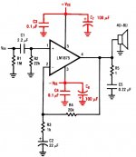
Okay, so I just have to do what I've colored in red on the datasheet. Thanks 🙂
I have one more question. The C1 capacitor is rated at 2.2µF ( connected to +IN ), but on the board it's a 0.1µF. Is that for decoupling or for a high-pass filter ? One of the two LM1875 dedicated to the subwoofer has a 22µF instead of a 0.1µF or 2.2 µF capacitor. I do not really understand why ...
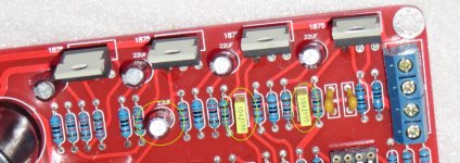
The three capacitors I'm talking about are circled in green in the attached photo.
Thanks for your help, it's really useful
Okay I understand 🙂 It's not surprising !
I have one more question. The C1 capacitor is rated at 2.2µF ( connected to +IN ), but on the board it's a 0.1µF. Is that for decoupling or for a high-pass filter ? One of the two LM1875 dedicated to the subwoofer has a 22µF instead of a 0.1µF or 2.2 µF capacitor. I do not really understand why ...
The three capacitors I'm talking about are circled in green in the attached photo.
Thanks for your help, it's really useful
What's an "audio grade" capacitor? Besides added marketing and price. If you want better caps, over voltage over ripple current and over temperature them. This will greatly increase there life.
Okay I understand 🙂 It's not surprising !
Attachments
C3 and C4 must be connected directly to each other.
The other ends of the two lead outs must connect directly to Pins 3 and 5.
C7 and C6 should be connected to each other.
The other two leadouts can use short traces/wires to connect to Pins 3 and 5.
Connect the two capacitor junctions together. This star is your Power Ground.
Connect C5 to the Power Ground.
There is a lot of tolerance to values for these decoupling caps.
0.1uF and 100uF works if you use the smallest package for each value.
But you can go to higher value if you can keep the package small.
I see. Thanks for your advice 🙂
Do you have any idea about the C1 0.1µF capacitor instead of the 2.2µF capacitor as described in my previous message ?
Do you have any idea about the C1 0.1µF capacitor instead of the 2.2µF capacitor as described in my previous message ?
2u2F is likely to be a film type.
These generally have a low esr.
You would probably need to add some series resistance to ensure stability.
That added resistance will increase the inductance and that in turn will ruin the effectiveness of the HF decoupling.
Stay with X7R ceramic and buy as high value @ the voltage you require in the smallest package, probably 805, but maybe 1208.
- Status
- Not open for further replies.
- Home
- Amplifiers
- Power Supplies
- Capacitance vs Ripple current