I'm sorry, but I didn't understand what you mean 🙁
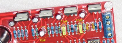
Have a look at he image I joined, the two 0.1µF film capacitors are connected to the " sound input " of the LM1875. The recommended value on the LM1875 datasheet is 2.2µF but these film capacitors are 0.1µF only. The 22µF capacitor has the same role as the 0.1µF film capacitors, but it's a 22µF cap. The two 0.1µF film caps is on the L and R channels, while the 22µF is connected on the subwoofer channel. Why different values ? I guess there is a reason for it.
If only I hadn't needed a 2.1 amplifier I would have built the whole amplifier so I wouldn't ask so many questions about this 2.1 board
Another question : do you think the two LM1875 amplifying the sub need HF and/or MF decoupling ? 🙂
Thank you for your patience
Attachments
Last edited:
Remember what Andrew said:
Treble may benefit from a "quick" 100 nF film cap, while 22 µF
may improve bass performance. Guess the designer did some
measurement for evaluation or at least some simulations, but
basically that should be the (quite common) idea behind.
There is a lot of tolerance to values for these decoupling caps.
Treble may benefit from a "quick" 100 nF film cap, while 22 µF
may improve bass performance. Guess the designer did some
measurement for evaluation or at least some simulations, but
basically that should be the (quite common) idea behind.
Thanks, it's clear now 🙂 What is strange is that the PCB marking is 2.2µF and the capacitor is a 22µF so was it an error during the PCB assembly or something else, I don't know. As long as it doesn't have an impact on the sound it's all right
Certainly no error. Fitting a super low ESR film cap to the higher frequency channels
and a higher capacitance lytic to the bass section seems absolutely logical to me.
Again, there is a lot of tolerance.
However, feel free to fit both a 100µF lytic + a 100nF film type to any of the channels
if you feel better with this.
and a higher capacitance lytic to the bass section seems absolutely logical to me.
Again, there is a lot of tolerance.
However, feel free to fit both a 100µF lytic + a 100nF film type to any of the channels
if you feel better with this.
Ok thanks 🙂
So, I'm going to put decoupling capacitors on the four LM1875 and on the two NE5532 op amp power supply.
In order to save space, do the two LM1875 powering the sub need MF and HF decoupling ?
I think I will order the capacitors tomorrow
So, I'm going to put decoupling capacitors on the four LM1875 and on the two NE5532 op amp power supply.
In order to save space, do the two LM1875 powering the sub need MF and HF decoupling ?
I think I will order the capacitors tomorrow
The HF decoupling (using X7R) must be on the device power pins or VERY CLOSE, (1mm or 2mm).
The MF decoupling (using electrolytic) can be a bit further away from the Power Pins, maybe 5mm to 15mm.
This longer distance ( for MF decoupling) could allow one decoupling electro to service two chips' +ve power pin. Another electro could service two chips' -ve power pin.
Is this description talking about Power Pin decoupling capacitors?
Have a look at he image I joined, the two 0.1µF film capacitors are connected to the " sound input " of the LM1875. The recommended value on the LM1875 datasheet is 2.2µF but these film capacitors are 0.1µF only. The 22µF capacitor has the same role as the 0.1µF film capacitors, but it's a 22µF cap. The two 0.1µF film caps is on the L and R channels, while the 22µF is connected on the subwoofer channel.
Putting less electrolytics will allow me to save some space on that PCB 🙂
The description isn't about the power pin decoupling capacitors but about the decoupling capacitor on the signal path, right before entering the chip 🙂 In fact I was just wondering why the capacitors do not respect the LM1875 datasheet, and ticktock answered.
The description isn't about the power pin decoupling capacitors but about the decoupling capacitor on the signal path, right before entering the chip 🙂 In fact I was just wondering why the capacitors do not respect the LM1875 datasheet, and ticktock answered.
Are you enquiring about DC blocking capacitors, or power rail decoupling capacitors?
Post10 was the first where closeness to chips came in.
Post17 left pic, is clearly about power rail decoupling capacitors. What about all your other questions?
Post10 was the first where closeness to chips came in.
Post17 left pic, is clearly about power rail decoupling capacitors. What about all your other questions?
Last edited:
In the #17 I was talking about the C1 capacitor which is connected to the audio signal pin, the pin 1 ( +IN ), as described on the drawing I joined 😱
In fact in the #17 I switched to another question in the second part of the message, a question which was about other capacitors 🙂 Then ticktock answered, so for the moment I do not have any question left 🙂
Many thanks for your help about power decoupling capacitors, I was lost but now I know what to do
The HF decoupling (using X7R) must be on the device power pins or VERY CLOSE, (1mm or 2mm).
Why do you insist on X7R, Andrew? Why not C0G/NP0, such as these TDK?
TDK C0G
Is it a cost consideration?
I also chose C0G/NP0, but I noticed they are bigger than X7R 🙁 And X7R are cheaper too, but not as good.
From testing and experiment by other Members of the Forum, it seems that X7R have about the right amount of esr to attenuate ringing when added to an existing LC circuit.
I have not seen equivalent testing reports confirming that the lower esr of C0C/NP0 meet the attenuation requirement.
I have seen a couple of statements that NP0 are OK for decoupling, but that is very far away from testing.
It has absolutely NOTHING to do with COST.
It has much to do with size and inductance and esr and values that are available.
Try to find a 1uF 100V smd NP0 at a size that fits on the Pins of a chipamp. Can you find a 1uF 100V NP0 leaded that is small?
There are some 25V and a very few 50V
Last edited:
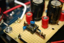
Those TDK C0G/NP0 ceramics are quite small. Here's a shot from an old project of mine using 100nF TDKs.
Attachments
Last edited:
Okay, so I stay with X7R 🙂
Here are some of the the capacitors I've chosen :
Power supply capacitors : UVK1V682MHD Nichicon | Mouser
Input capacitors ( ELNA Silmic II ) : RFS-50V4R7ME3#5 Elna | Mouser
MKP capacitors for audio signal decoupling : MKP1837410011 Vishay / Roederstein | Mouser
Ceramic X7R capacitor for power supply decoupling : K104K15X7RF5TH5 Vishay / BC Components | Mouser
Electrolytic capacitor for power supply decoupling : UPW1V101MPD Nichicon | Mouser
Those TDK ceramics are quite small. Here's a shot from an old project of mine using 100nF TDKs.
It's true, they seem to be quite small ! But Andrew recommends X7R so I think I'll stick with X7R 🙂
Can I assume that the black dot on the top of the caps indicates NP0?
AndrewT regurgitates the knowledge of others more knowledgeable than me.
Those tdk in post 35 are far smaller than the vishay/BC in post 36.
AndrewT regurgitates the knowledge of others more knowledgeable than me.
Those tdk in post 35 are far smaller than the vishay/BC in post 36.
Can I assume that the black dot on the top of the caps indicates NP0?
Yes, the black dot means NP0.
I've found those to be quite good for opamp decoupling in my limited experience with them. Usually I prefer to play with tubes...;-). I've even used those TDKs for noise shunts from the pins of tube heater supplies when I can't fit a Multicap film cap (my favorite for that particular application).
- Status
- Not open for further replies.
- Home
- Amplifiers
- Power Supplies
- Capacitance vs Ripple current