Mark: I guess when one orders 20 or so PCBs and part sets price drops quite a bit as your original post implies.
Here is the math. OSH Park charges 34.90USD for 3 boards. USPS charges 3.22USD for shipment of 8oz in a padded envelope, which costs itself as well. PayPal charges 3.75%.
As for the full kit, the BOM on Mouser rang up 26.32USD with 4 0.1% resistors and the test per Borse's BOM update. I am not going to split headers to ship several pins with each board. USPS priority mail small box is 5.95.
Thank you again for sharing the expertise.
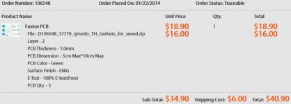
For those who don't mind if the PCB boards are made in China, I also have some V4 boards with ENIG (gold plated surface finishing) from Seeed Studio, and will be happy to part with them at USD9 + shipping. They cost me USD40.9 for 5 boards, so at cost for me is USD9, taking into account the protective envelope and Paypal charges.
I don't have full kits on offer though.
I don't have full kits on offer though.
Attachments
Could the quasimodo potentially be used to test for ringing and find the zobel network values in (tube) output transformers?
Hi Mark,
Does it matter if I use 4.97k instead of 4.7k for R2?
I only found I bought 4.97k instead of 4.7k after I return home from a shop.
In HK, it is very often 2 types of resistors are put the same drawer.
I am so lucky~~
Does it matter if I use 4.97k instead of 4.7k for R2?
I only found I bought 4.97k instead of 4.7k after I return home from a shop.
In HK, it is very often 2 types of resistors are put the same drawer.
I am so lucky~~
Just curious to know if the Quasimodo can be used in the following way, shown in figure 2?
http://cds.linear.com/docs/en/application-note/an104f.pdf
It seems to me that the Quasimodo and the LTC-1693-1 + FET are doing the same thing.
Right?
http://cds.linear.com/docs/en/application-note/an104f.pdf
It seems to me that the Quasimodo and the LTC-1693-1 + FET are doing the same thing.
Right?
I don't have much experience with valves or output transformers for valve amplifiers, so what follows below might be utterly irrelevant.Could the quasimodo potentially be used to test for ringing and find the zobel network values in (tube) output transformers?
You could certainly use Quasimodo to measure the leakage inductance of the transformer secondary (QM design note, appendix C), by resonating it with a few different Cx capacitor values, then extracting Lleakage_sec via linear regression.
You could do the same thing to measure the leakage inductance of the primary too; just short the secondary and Quasimodo_appendix_C_verb the primary.
Now that you know the secondary leakage inductance (and, since it pops out of the linear regression with no extra work, you also know the secondary capacitance), perhaps you could plug those numbers into your design formulae, and get an optimized zobel network for your valve amplifier's output transformer.
The above is wild speculation from a severely-lacking-in-valve-expertise guesser.
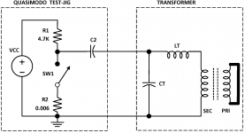
Perform a bit of circuit analysis on Figure 2 of the design note (p.3), reproduced below.Does it matter if I use 4.97k instead of 4.7k for R2?
Assuming that the switch opens and closes 120 times per second with 50% duty cycle, what is the maximum pullup resistance Rmax that gives acceptable performance? What is the minimum pullup resistance Rmin that gives acceptable performance? Does 4.7k fall between Rmax and Rmin? Does 4.97k?
Attachments
... figure 2 of ... http://cds.linear.com/docs/en/application-note/an104f.pdf
It seems to me that the Quasimodo and the LTC-1693-1 + FET are doing the same thing. Right?
Please take a look at the first paragraph on page 3 of the Quasimodo design note. It includes these remarks
Capacitor C2 injects a high-to-low voltage step into the resonant circuit. ... Please note that Quasimodo is AC coupled to the transformer, there is no DC current path ...
Has anyone applied their Quasimodo to LARGE transformers (more than 1000 volt-amperes)? I received a PM from a Quasimodo user who wishes to compare notes and share experiences. Unfortunately the largest trafo I've got is only 400VA so I am not in the target audience. Anyone?
Hi Mark,
I have just had the opportunity to measure a 1000 VA transformer which I borrowed from a kind hifi-buddy. Specs: Prim.: 230 V, 50/60 Hz. Sec.: 4 x 22 V, 11,4 Amp.
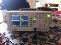
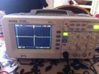
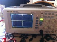
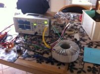
I used both the Quasimodo V3 and QV4 editions. Both worked flawlessly and like a charm. I have attached a few pitures and I am sorry for the lousy pic-quality from my phone.
On my new scope it is possible to load the curves from the scope directly on a USB-stick. Unfortunately I didn´t have too much luck with this. I think I have to read the manual one more time to get this right 😱. Otherwise, there might be some good instructional videos on YouTube out there (?).
So, as I experienced it is absolutely no problem for the QV3 and QV4 to "drive" a large transformer. Measureing the 1000 VA transformer was carried-out in exactly the same way as some of my small transformers - and with same ease.
First picture is a secondary winding without snubber. Pic. 2 + 3 are secondary windings with snubbers. Pic. 4 is the test set-up with the scope, the transformer and (difficult to see left in the picture) the QV3.
Kind regards
Karsten 🙂
Attachments
Last edited:
Did you short all the primaries and three of the secondaries?
What are the component values of the snubber?
What are the component values of the snubber?
Hi Andrew,
Yes, primary and all secondaries were shorted - except the one being measured, of course 😀
My HiFi-buddy is going to use the secondaries as pairs ie. the secondaries 1+ 2 are parallelled and secondaries 3+4 are parallelled. The wires were paired according to the colours of the wires as recommended by the manufacturer (paying attention to the phase of the windings, I think).
I ended-up with 6,8 Ohms for the first one and 6,0 Ohms for the second one.
Before measuring the parallelled secondaries I measured the first "ordinary", single secondary winding. This was 7,5 Ohms. I only measured this winding for adjustment of my scope, though.
The cap-sizes were "as usual" 0,15 µF i series with R (trim-pot) and 0,01 µF parallel to the RC-section.
Kind regards
Karsten
... I have just had the opportunity to measure a 1000 VA transformer which I borrowed from a kind hifi-buddy. ... I used both the Quasimodo V3 and QV4 editions. Both worked flawlessly and like a charm. I have attached a few pitures ... So, as I experienced it is absolutely no problem for the QV3 and QV4 to "drive" a large transformer. Measureing the 1000 VA transformer was carried-out in exactly the same way as some of my small transformers - and with same ease.
Thank you, Karsten! I am sure the author of post #312, who asked for people's experiences and results using QM on a large transformer, is very grateful as well.
Unfortunately, my digital scopes are in a moving van at the moment, so I'm unable to make a tutorial How-To about capturing waveform data on a USB thumb-drive (flash memory). I seem to recall that the steps are something approximately like:
- insert USB drive
- get waveform you like on scope
- select Storage
- CSV
- External
- File
- New File
- key in file name using their confusing twist-knob-to-type interface
- Save
- return
- return.
I ended-up with 6,8 Ohms for the first one and 6,0 Ohms for the second one.
For those who have advanced beyond the "Quasimodo Beginner" status, I offer a couple of remarks. They are neither suggestions nor advice; merely statements that you may wish to consider (or to disregard).
IF you use Quasimodo to optimize a transformer snubber, and if you find the optimum snubber resistance value Rs to be uncomfortably low (under 20 ohms? under 10 ohms?), in your own opinion, based upon your own experience, taste, and good judgement, ...
THEN you might think about decreasing the value of the across-the-secondary capacitor "Cx" and optimizing again, to get a larger Rs value, to make yourself feel better.
THEN you might think about decreasing the value of the across-the-secondary capacitor "Cx" and optimizing again, to get a larger Rs value, to make yourself feel better.
This is certainly not necessary; you've already got an optimum snubber which gives critical damping with zeta=1 and you've seen it do its snubbing job with your own eyes on your own scope. So you don't need to fiddle with it.
However if you want to fiddle with it, if you simply don't like your Rs because it's uncomfortably low, one way to fiddle with it is to decrease Cx and optimize again. Don't do this unless you consider yourself quite a bit more advanced than a Beginner Quasimodo User.
You can keep Cs the same {since (Cs/Cx > 15) was true before decreasing Cx, therefore (Cs/Cx > 15) is even more true after the decrease} , OR you can decrease Cs by the same factor. Choose whichever seems best to you.
If you don't want to capture waveform data as (t, voltage(t)) points, and instead you simply want to perform a "screen image capture" from a Rigol digital scope to a USB drive, the steps are similar:
- insert USB drive
- get waveform you like on scope
- select Storage
- Bitmap
- External
- File
- New File
- key in file name using their confusing twist-knob-to-type interface
- Save
- return
- return.
Are there any boards available for this?
Post#1 of this thread includes attachments of the "Gerber files" that a PCB fab house needs, to build boards for you. Post#1 also includes this remark:
.... diyAudio members who have ordered their own sets of PCBoards from seeed and/or OSH Park, using the Gerbers provided here, include: gazzagazza, luvdunhill, Borges, stormsonic, cwtim01. You can PM them to find out how easy or difficult it was.
Perhaps I should also mention, there is another thread here on diyAudio which discusses a simpler & cheaper version of Quasimodo that can be slapped together on a solderless breadboard ("plug-in protoboard") in a couple of hours. For those who don't want or need a dedicated printed circuit board. (link to CheapoModo thread)
Are there any boards available for this?
I am building up a rectifier to power up a 21st Century Maida regulator with an old transformer I have in hand and stumbled across this thread when I searched for Snubbers.
I too am looking for a board. BigE - let me know if you will place a PCB order and we can split the costs. I will PM you with details
While you are waiting for your PCB to arrive, you could assemble a CheapoModo on your protoboard and do some preliminary testing. Only takes a couple of hours.
I have a few extra V4 boards with HASL finish from Seeed Studio batch. Can sell them for 10 EUR (including shipping and Paypal fees) for European buyers or 12 EUR for the rest of the world. PM me if interested.
Great and very clear guide! I've done this technique on audio transformers before (optimising square wave response at 10kHz, much smaller values mind) but for some reason didn't apply it to mains transformers!
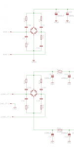
Perhaps unfortunately, what I did do was expect to calculate snubbers of this (Zobel) style:
http://www.diyaudio.com/forums/solid-state/112453-nap-140-clone-amp-kit-ebay-38.html#post3556518
so my schematic shows and my PCB has pads for these parts:

Today I have measured my transformers (24VA each) in accordance with the data presented in the Qausimodo PDF. I built a quick 120Hz square wave oscillator driving the transformer with an N-Mos. The effect of the snubbers was clear, and I obtained the best response using 10nF CX, 100nF CS, 430R RS (9V) and 450R RS (12V CT).
So, what I wonder now is how/if I can apply this to the snubber arrangement I've left on the PCB, or if I'm simply better off applying it directly on the transformer outputs (they're on their own little board, of course the AC connection lead will be short) as shown in the PDF. Or, perhaps a combination with CX capacitor on the transformer output and the Zobel snubbers adjusted in value to suit a full bridge and applied to the PCB?
Thanks for the great work on this topic and any input appreciated!
Perhaps unfortunately, what I did do was expect to calculate snubbers of this (Zobel) style:
http://www.diyaudio.com/forums/solid-state/112453-nap-140-clone-amp-kit-ebay-38.html#post3556518
so my schematic shows and my PCB has pads for these parts:
Today I have measured my transformers (24VA each) in accordance with the data presented in the Qausimodo PDF. I built a quick 120Hz square wave oscillator driving the transformer with an N-Mos. The effect of the snubbers was clear, and I obtained the best response using 10nF CX, 100nF CS, 430R RS (9V) and 450R RS (12V CT).
So, what I wonder now is how/if I can apply this to the snubber arrangement I've left on the PCB, or if I'm simply better off applying it directly on the transformer outputs (they're on their own little board, of course the AC connection lead will be short) as shown in the PDF. Or, perhaps a combination with CX capacitor on the transformer output and the Zobel snubbers adjusted in value to suit a full bridge and applied to the PCB?
Thanks for the great work on this topic and any input appreciated!
Attachments
- Home
- Amplifiers
- Power Supplies
- Simple, no-math transformer snubber using Quasimodo test-jig