Hi there,
I found this forum while googling for ideas of troubleshooting/repairing a tape recorder. I'm a musician and electronic newbie but always willing to learn more to manage my own repairs of my gear. So I'm turning to you. This post got ridiculously long, since I've tried to collect all info I can give.
If anybody of you experts would take the time to read, write and help me troubleshoot I'd be most grateful!
My old 4-track multitracker doesn't work. It did ten years ago. It's a Fostex XR-5 (similar to X-55), a mid-/entrylevel machine at the time. So it's not valuable enough to have a pricey tech fix it. Still, I'm up for the challenge of DIY.

What's wrong?
When plugging it in/switching it on - the green LED for power and the red LED for record reacts (blinks once) but remain unlit.
When pressing PLAY: The mechanical tape transport seems to work. It plays, rewinds and fast forwards.But there's no sound/no output. Not from the headphone jack, nor from the stereo outs or the monitor outs. The mixer led-display ("VU-metering") is totally dark, both when playing back recorded tapes and when set to monitor incoming microphone signals.
Dummy-checks done:
I have the original power supply 12 VDC, and I've also tried another one with
I have tested it with cassettes known to be recorded with sound.
I tried to do a test recording (handclaps) on a used cassette with music on. I took the cassette to play it back on another machine, but no sound had been recorded, neither had any of the old music been deleted (by the 4-track eraser head).
What I have tried:
I opened the machine. It consists of 5 connected circuit boards plus the tape transport unit.

A small powerswitch/jack-pcb
A big PCB marked R/P (assuming it means recorder/player)
A big PCB with all the controls on the mixer
A small PCB for the LED Display (VU-meters)
And a long thin stripe with all the different outs/AUX-send-jacks at the top.
Visual inspection tells me nothing, I can't see anything fried or any solder joints loose.


I dismounted the tape transport unit and used an electronic cleanerspray (alcohol based, non-lubricating et) to clean the switches for rec/play etc. (Small copper tongues being pushed together when pressing the buttons for play/rec etc.)
In a similar way I cleaned all jacks, all switches and pots in the machine
When a "noob" thinks out loud:
I am the original owner, prior to this, this machine has never been opened. It has not taken a beating, fallen to the floor or any such thing. It has NOT lived its life in a dust free environment. Oxide or dust seemed like a good place to start.
Why doesn't the green power LED remain lit when the power is turned on?
- Is there something broken in the power-on switch on the back?
-
Why is there no sound when a tape is playing?
- Is the playback head not getting any "power"?
- Is there some broken link between the mixer/output section and the recorder/player?
Resources:
I do not have the service manual and haven't been able to find one.
I have soldering gear and a Multimeter.
Thankyou very much for reading. If anybody has tips or ideas on checks I can do I would very much appreciate it.
Cheers,
Carl
I found this forum while googling for ideas of troubleshooting/repairing a tape recorder. I'm a musician and electronic newbie but always willing to learn more to manage my own repairs of my gear. So I'm turning to you. This post got ridiculously long, since I've tried to collect all info I can give.
If anybody of you experts would take the time to read, write and help me troubleshoot I'd be most grateful!
My old 4-track multitracker doesn't work. It did ten years ago. It's a Fostex XR-5 (similar to X-55), a mid-/entrylevel machine at the time. So it's not valuable enough to have a pricey tech fix it. Still, I'm up for the challenge of DIY.
What's wrong?
When plugging it in/switching it on - the green LED for power and the red LED for record reacts (blinks once) but remain unlit.
When pressing PLAY: The mechanical tape transport seems to work. It plays, rewinds and fast forwards.But there's no sound/no output. Not from the headphone jack, nor from the stereo outs or the monitor outs. The mixer led-display ("VU-metering") is totally dark, both when playing back recorded tapes and when set to monitor incoming microphone signals.
Dummy-checks done:
I have the original power supply 12 VDC, and I've also tried another one with
I have tested it with cassettes known to be recorded with sound.
I tried to do a test recording (handclaps) on a used cassette with music on. I took the cassette to play it back on another machine, but no sound had been recorded, neither had any of the old music been deleted (by the 4-track eraser head).
What I have tried:
I opened the machine. It consists of 5 connected circuit boards plus the tape transport unit.
A small powerswitch/jack-pcb
A big PCB marked R/P (assuming it means recorder/player)
A big PCB with all the controls on the mixer
A small PCB for the LED Display (VU-meters)
And a long thin stripe with all the different outs/AUX-send-jacks at the top.
Visual inspection tells me nothing, I can't see anything fried or any solder joints loose.
I dismounted the tape transport unit and used an electronic cleanerspray (alcohol based, non-lubricating et) to clean the switches for rec/play etc. (Small copper tongues being pushed together when pressing the buttons for play/rec etc.)
In a similar way I cleaned all jacks, all switches and pots in the machine
When a "noob" thinks out loud:
I am the original owner, prior to this, this machine has never been opened. It has not taken a beating, fallen to the floor or any such thing. It has NOT lived its life in a dust free environment. Oxide or dust seemed like a good place to start.
Why doesn't the green power LED remain lit when the power is turned on?
- Is there something broken in the power-on switch on the back?
-
Why is there no sound when a tape is playing?
- Is the playback head not getting any "power"?
- Is there some broken link between the mixer/output section and the recorder/player?
Resources:
I do not have the service manual and haven't been able to find one.
I have soldering gear and a Multimeter.
Thankyou very much for reading. If anybody has tips or ideas on checks I can do I would very much appreciate it.
Cheers,
Carl
Well, hi!
If the Led doesn't light...what about checking from the power supply input to the regulator ? I see the Pitch is the pot near the heatsinked ( !?) transistor, so that's not a 9 V tension regulator...nevermind.
So the only tension available is the one that powers the motor, the other parts seems to be cutted away from the supply.
You can look at the datasheets of the various ICs and see where the Vs is applied, so test if they get the right supply.
You could divide the two PCBs and try each one indipendently ( easy to say !!)
Well, hi!
If the Led doesn't light...what about checking from the power supply input to the regulator ? I see the Pitch is the pot near the heatsinked ( !?) transistor, so that's not a 9 V tension regulator...nevermind.
So the only tension available is the one that powers the motor, the other parts seems to be cutted away from the supply.
You can look at the datasheets of the various ICs and see where the Vs is applied, so test if they get the right supply.
You could divide the two PCBs and try each one indipendently ( easy to say !!)
Hi there,
Thanks for chiming in. I'll look into your suggestions! I also emailed Fostex to see if they can send me a Service Manual.
Here is the Power-PCB, if it provides any more clues. Thanks again!/C

BTW, if there are any other closeups that would give you a better view - please tell me and I'll shoot my best.
Hi,
That's what I thought: the wall adaptor provides 12V AC and not DC as you stated, right? Because that seems to be providing dual voltages from a single bipolar AC source.
That's what I thought: the wall adaptor provides 12V AC and not DC as you stated, right? Because that seems to be providing dual voltages from a single bipolar AC source.
Last edited:
No, it runs on DC. The original power supply gives 12VDC, 600mA, positive center polarity.
The machine also states that it wants 12 VDC on the back.
Thanks/C
The machine also states that it wants 12 VDC on the back.
Thanks/C
Jumping in with both feet first 😀
What is the DC voltage across each of the large caps on that little PCB ?
The device on the heatsink has been mentioned. What is the device type ? What is the voltage on all three pins (be very very careful not to short any out)
What is the device marking on the IC below that heatsink (the long black IC) ?


Hi!
Thanks all newcomers for chiming in. Like I tried to explain in my introducition I am truly a newbie. I can solder a loose joint, or follow instructions such as soldering small circuits (guitar fx-pedals) but this is my first adventure in electronics troubleshooting.
So this is the kind of newbie I am:
When measuring voltage, I measure from each leg to ground, right?
Thanks for your interest (and patience)
Measure the voltage on the 7810. What have you got on pins 1, 2 and 3 measuring from left to right ?
What is the device markings on that black IC ?
What is the device markings on that black IC ?
Hi!
Thanks all newcomers for chiming in. Like I tried to explain in my introducition I am truly a newbie. I can solder a loose joint, or follow instructions such as soldering small circuits (guitar fx-pedals) but this is my first adventure in electronics troubleshooting.
So this is the kind of newbie I am:
When measuring voltage, I measure from each leg to ground, right?
Thanks for your interest (and patience)
Yes, black meter lead on ground and read to the various points with the red lead.
Oh... here comes stupid.
I did manage not to be careful. First I managed to short the first leg to the heatsink, and then (sigh) I managed to short the middle leg too.
This caused the last leg to show approx 18 V, which it didn't show before so I switched the power off.
I guess I need a new regulator now - before I can go into detective mode again?
Thanks/C
Its easily done but you must be careful. The regulator shouldn't have been harmed by that... if it was OK to begin with.
Have another measure and report back with the voltages on each leg. If its easier then try measuring on the print underneath.
Does the middle leg go to ground ?
Have another measure and report back with the voltages on each leg. If its easier then try measuring on the print underneath.
Does the middle leg go to ground ?
With the multimeter set like this:
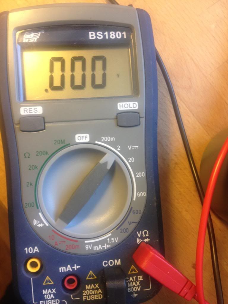
I get the following readings (left to right, measured from front with printed numbers)
First leg: 1. (it just reads like that)
Middle leg: .497 ( I get the same reading when I measure ground to the heatsink)
Third leg: .205
I get really confused with the decimals with these things. ;-)
I get the following readings (left to right, measured from front with printed numbers)
First leg: 1. (it just reads like that)
Middle leg: .497 ( I get the same reading when I measure ground to the heatsink)
Third leg: .205
I get really confused with the decimals with these things. ;-)
The first leg reading is strange, since the multimeter doesn't move "back and forth". It's just this one number.
Your meter looks to be set OK... well actually the 1.00 could be over-range. Set it to 20 volts and remeasure.
I'll have to leave it for while...
I would think you should have at least 15 volts on the left leg. The middle leg at 0.497 volts suggests it connects to that diode ? at the side of the regulator. If so then that reading is OK. The right hand pin is the output and should be at approx 10 volts plus the 0.497 volts. So around 10 to 11 volts on that right hand pin.
If the voltage is going in to the reg but there is no 10 volts coming out then the next step is to isolate the output leg (the right hand one) and measure again on the unconnected pin.
If there is voltage going in and nothing coming out though, then its a fair chance the reg is faulty... whether there are other issues though would remain to be seen. The 7810 is an uncommon device but thats no problem. We can fit a 7805 and make it into a 7810 with just one diode... we'll come to that when you confirm the readings.
BTW, all those readings were with the "power on". With the power switch set to "stand-by" I get different readings:
Leg one: Seems to hold a voltage still, but it drains - I get smaller and smaller readings.
Middle leg: Zero
Third leg: Zero
Leg one: Seems to hold a voltage still, but it drains - I get smaller and smaller readings.
Middle leg: Zero
Third leg: Zero
With the Multimeter range set to 20V I get the following readings:
Leg 1: 11,8 V
Leg 2: 0,49 V
Leg 3: 0,21 V
Leg 1: 11,8 V
Leg 2: 0,49 V
Leg 3: 0,21 V
- Status
- Not open for further replies.
- Home
- Source & Line
- Analogue Source
- 4-track cassette repair - sharp troubleshooters welcome!