Leg one: Seems to hold a voltage still, but it drains - I get smaller and smaller readings.
Pin 1 input - You're just measuring the discharging of the capacitors!
Jumping in with both feet first 😀
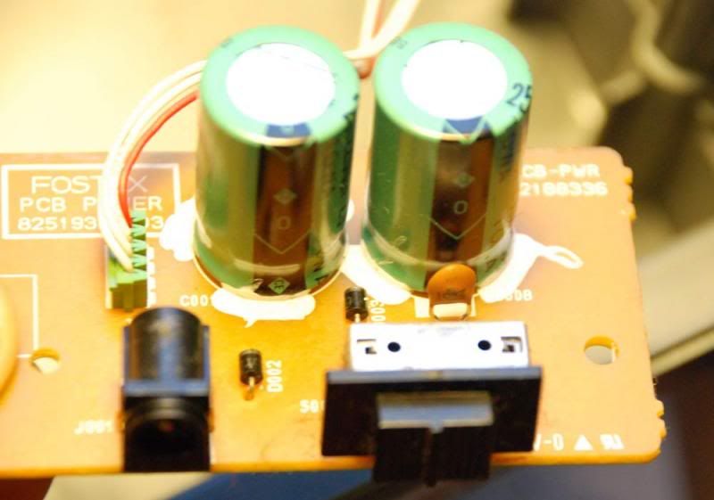
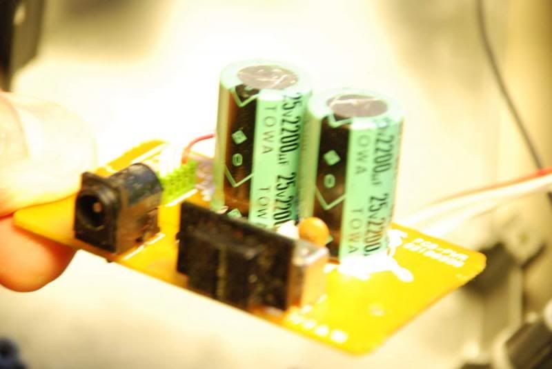
What is the DC voltage across each of the large caps on that little PCB ?
The DC Voltage measured to ground is:
11,8 V and 0,47 V (same on both caps, I measured each leg on each cap)
The device on the heatsink has been mentioned. What is the device type ? What is the voltage on all three pins (be very very careful not to short any out)
What is the device marking on the IC below that heatsink (the long black IC) ?
The long black IC reads:
MJM4556AL
JRC 6006H
The voltage at pin 1 seems too low for a 7810, they would normally work with around 14V or more at their input.
Power on for all these readings.
So you have approx 12 volts on Pin 1 and only 0.2 on pin 3. That 95% points to a faulty regulator. If I were faced with that situation, then my next step would be to unsolder just pin 3 from the board and measure the output directly on the floating pin. If it were still low then the reg is faulty. If the voltage appeared then I would then fit dummy load of say 100 ohms from pin 3 to ground and see if the reg could maintain the voltage.
If you don't want to do that then the easiest option (bearing in mind there could still be other issues) would be to replace the reg. If you can get a 7810 then all well and good but its an uncommon one in the series of 78xx devices. A 7805 and a small 5.1 volt zener can be used to "make" a new equivalent of a 7810 by adding the diode in series with the middle lead. Even easier... if that diode I mentioned next to the reg does indeed connect from the middle leg to ground then we can replace that diode with a 5.6 volt zener.
Sounds complicated 🙂 It isn't, it's two minutes of a job.
The DC Voltage measured to ground is:
11,8 V and 0,47 V (same on both caps, I measured each leg on each cap)
The long black IC reads:
MJM4556AL
JRC 6006H
The 4556 is a dual opamp. I wasn't sure whether the IC was used as a dual regulator of some sort, or a stereo output stage just by looking at the pictures. Seems as though its going to be audio.
The voltage at pin 1 seems too low for a 7810, they would normally work with around 14V or more at their input.
I would agree but even with a low voltage the output should be present (even if it is low and unregulated) an its not... so I'm thinking, lets work on what we know 100% as being incorrect readings 🙂
Its not easy without a circuit I know.
The voltage at pin 1 seems too low for a 7810, they would normally work with around 14V or more at their input.
Thanks,
Interesting. I don't know how things sum up.
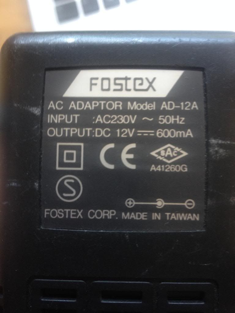
I measured the jack of my powersupply (not connected to the 4-track).
It reads 12.28 V. Since my other readings are 11.8 and 0.49, the sum of those seems to match incoming Voltage quite well?
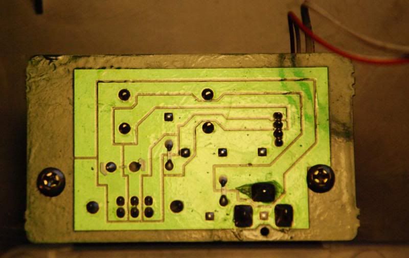
Can you possibly trace the circuit of the small PCB.
Do you mean, if I can find a schematic? Or can I take a better picture?
I emailed Fostex so maybe they have a service manual to send me.
/C
Power on for all these readings.
So you have approx 12 volts on Pin 1 and only 0.2 on pin 3. That 95% points to a faulty regulator. If I were faced with that situation, then my next step would be to unsolder just pin 3 from the board and measure the output directly on the floating pin. If it were still low then the reg is faulty. If the voltage appeared then I would then fit dummy load of say 100 ohms from pin 3 to ground and see if the reg could maintain the voltage.
If you don't want to do that then the easiest option (bearing in mind there could still be other issues) would be to replace the reg. If you can get a 7810 then all well and good but its an uncommon one in the series of 78xx devices. A 7805 and a small 5.1 volt zener can be used to "make" a new equivalent of a 7810 by adding the diode in series with the middle lead. Even easier... if that diode I mentioned next to the reg does indeed connect from the middle leg to ground then we can replace that diode with a 5.6 volt zener.
Sounds complicated 🙂 It isn't, it's two minutes of a job.
I like the idea of just changing a single component! ;-) So I called a local shop and sure enough, they have 7810 in stock! I will try to solder in a new one and see if I can get a new and better reading.
If there are more or other things wrong, then I might have to take another turn to the shop.
A big thankyou to everyone for helping me out so far!
Cheers/Carl
Well thats great that they have one. To unsolder parts I always use "solder braid" but for this you just heat all three pins together and pull although braid is always good to remove excess solder from the holes 🙂
This is solder braid in use,
http://www.diyaudio.com/forums/parts/127924-working-smd-how-do-without-specialised-tools.html
This is solder braid in use,
http://www.diyaudio.com/forums/parts/127924-working-smd-how-do-without-specialised-tools.html
Do you mean, if I can find a schematic? Or can I take a better picture?
I emailed Fostex so maybe they have a service manual to send me.
/C
No, can you draw your own schematic using the PCB as it is very simple.
Can you take a photo of the label on the PSU.
Can you take a photo of the track side of the little PCB.
Can you take a photo of the track side of the little PCB.
I was sure that someone- and I was sure it was K&D's turn 😱- was going to post it 😛
Yes, it would be useful to make sure about the thing I said, about being a dual voltage supply ( plus and minus referred to ground ) made from a single Ac source . I wasn't very sure. So it must be a dual supply !😕
All electronics works by electricity and the PSU ( power supply unit ) in audio devices is very important.
The regulator needs at least +3V on the input to get the desired output voltage
A 12 V source after rectification and levellement ( diodes and caps ) and without load is 17,5-19 V ( it is V*1,5 )
Hi again,
Thanks KatieandDad and picowallspeaker for not giving up on there being something wrong with my readings etc. It made me question myself and doing some extra checks.
Well, I have two 12VDC-power supplies at home, the original one and another that's originally for a standalone hard disc. This morning I took my readings from the NOT original powersupply (stupid me).
When I measured them both, the original PSU delivered approx 17 V, compared to 12.2 V for the hard disk PSU. (Unregulated vs regulated powersupply, right?).
Anyway - I did buy and solder a new 7810.
My new readings on the three legs (with the original power supply) is now:
Leg 1: 9.4V
Leg 2: 5.04V
Leg 3: 5.01V
Does that make better sense? I did take shots of the power PCB and my PSU... but do you know what! When I put it altogether the green Power LED shines steady. And when playing back a tape there is sound in the headphones and the LED Display (VU-meters) are showing signals on all four tracks.
Thanks a lot Mooly and all of you!
I might be back with different questions. It seems the machine is really bad at fast forwarding, although it rewinds well. Maybe I need to change some motor or something as well?
But thankyou all for now, I'm going to test-drive it first!
/Carl
🙂 Good to hear you have it working. So from what you say, a new reg has brought it to life. Yes, regulated vs unregulated for your two supplies.
Belts friction surfaces and clutches are the main mechanical problems for rewind/fast forward troubles.
(Those new readings are all highly suspect 😀 something isn't right somewhere... perhaps your measurement technique or where you are referencing the readings to)
Belts friction surfaces and clutches are the main mechanical problems for rewind/fast forward troubles.
(Those new readings are all highly suspect 😀 something isn't right somewhere... perhaps your measurement technique or where you are referencing the readings to)
So, the meaning of this thread is " Why do they write 12VDC if the required and usable output should be at least 14-15 V " ??
Hmmm, that's exactly the voltage of a car battery .
And this unit is meant for recording on 4 tracks, so musicians...on the road!
So it should be intended as ( but now we know that the 7810 needs at least 13V on the input to deliver 10 V at leg 3 )
....Uh sorry! Well, loaded Vs unloaded supply !
Hmmm, that's exactly the voltage of a car battery .
And this unit is meant for recording on 4 tracks, so musicians...on the road!
So it should be intended as ( but now we know that the 7810 needs at least 13V on the input to deliver 10 V at leg 3 )
....Uh sorry! Well, loaded Vs unloaded supply !
Anyway - I did buy and solder a new 7810.
My new readings on the three legs (with the original power supply) is now:
Leg 1: 9.4V
Leg 2: 5.04V
Leg 3: 5.01V /Carl
The above voltage readings make no sense ?
According to the specs the 7810 only requires 2V extra to maintain its output voltage,
7810A regulator ... - Datasheet Search Engine Download
Many of the newer LDO regulators of today require less than that.
FWIW
jer 🙂
P.S. I am glad you got it running !!! 🙂
7810A regulator ... - Datasheet Search Engine Download
Many of the newer LDO regulators of today require less than that.
FWIW
jer 🙂
P.S. I am glad you got it running !!! 🙂
Hi again,
Haven't had time to really try out the machine. If I could do something more to make it perform better I'm all in for it!
So, here are the pics of the small power PCB.
This is the lettering on the PSU:
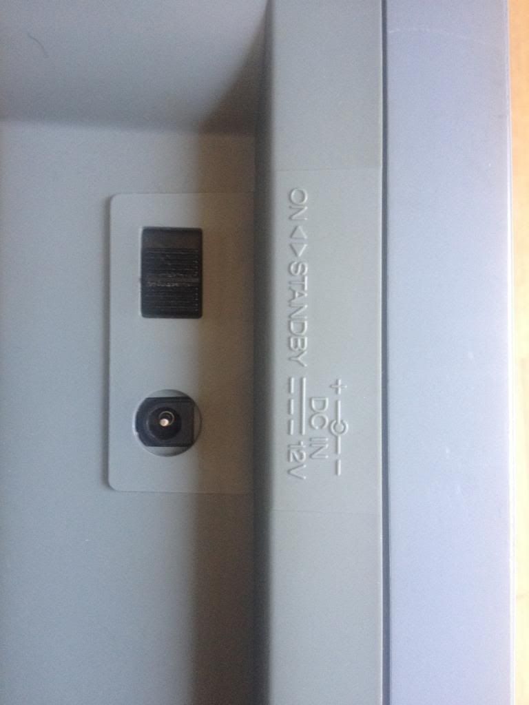
And on the back of the machine:
Haven't had time to really try out the machine. If I could do something more to make it perform better I'm all in for it!
So, here are the pics of the small power PCB.
This is the lettering on the PSU:
And on the back of the machine:
- Status
- Not open for further replies.
- Home
- Source & Line
- Analogue Source
- 4-track cassette repair - sharp troubleshooters welcome!