I am actually tending to an ultra simple approach plus AFEC.
I simmed a diamond input stage driving a single transistor TIS and EF2 and get 30 ppm at 420 watts out, and less than 10 ppm at 50 watts out ( both at 20 kHz). For AFEC part, I used the LF356 model in the LTspice library.
PSRR is better than 100 dB out to 10s of KHz - you need cap multipliers in the rails to get this type of performance normally.
.
.
Daniel why don't we move this discussion to it's own thread since it's been deemed off topic.
Manso,
That is an interesting design you just posted. Can you tell us something about it for us laymen? It looks very different than what I have seen, I'm not sure I can follow all that is going on there. Just a brief description of how that topology is working would be nice.
That is an interesting design you just posted. Can you tell us something about it for us laymen? It looks very different than what I have seen, I'm not sure I can follow all that is going on there. Just a brief description of how that topology is working would be nice.
The maximum power transfer theorem.
https://www.princeton.edu/~achaney/tmve/wiki100k/docs/Maximum_power_theorem.html
When the source impedance is roughly that of the load impedance the power transfer is at maximum, top of the curve. If the source impedance is lower than the load then it's more efficient.
This would be applicable if the amplifier were the power source - it is not! The mains are the power source, which have a very low impedance. The transformer is the largest impedance between load and mains at full power, so it is what we need to match to the impedance of the speaker. The amplifier is a load just like the speaker, and the power it wastes, doesn't go to the speaker.
Simplifed CFA - it's time for them-
New and simplified CFA (also called CFOA in latest published book) would be good to explore. How to keep Classic CFA features and characteristics at the same time simplifying.
[BTW - Many years ago I tried using two mono blocks of very high power and low THD for a power supply to a lower power amp. After some fiddling with the circuitry, I biased the mon-block amps to +50vdc output and the other at -50Vdc. Then powered another lower power amp with them -in place of the lower power amp's PS - just to see what they would sound like. Very 😎]
OK back to Simplified CFA.
THx-RNMarsh
Last edited:
In Manso's schematic, almost all of the gain is at the collectors of Q54 and Q55. The current gain of the output stage will determine load-dependent distortion; if it is high enough, the C-B leakage of the transistors around this point will be the dominant source of distortion which will not be signal-dependent, and not load-dependent. This schematic has some useful ideas, but it would need to be adapted and adjusted to be used for an audio power amp.
Also, Q26 is the wrong polarity and should have it's emitter at the base of Q33. I think this is a strange error to make if the person who designed it draws the schematic, but I've seen this kind of thing multiple times in patent drawings and textbook schematics. Just sort of strange to me.
Also, Q26 is the wrong polarity and should have it's emitter at the base of Q33. I think this is a strange error to make if the person who designed it draws the schematic, but I've seen this kind of thing multiple times in patent drawings and textbook schematics. Just sort of strange to me.
I am actually tending to an ultra simple approach plus AFEC.
I simmed a diamond input stage driving a single transistor TIS and EF2 and get 30 ppm at 420 watts out, and less than 10 ppm at 50 watts out ( both at 20 kHz). For AFEC part, I used the LF356 model in the LTspice library.
PSRR is better than 100 dB out to 10s of KHz - you need cap multipliers in the rails to get this type of performance normally.
.
.
Are you ready to show us where you are with circuitry, yet?
THx-RNMarsh
Also, Q26 is the wrong polarity and should have it's emitter at the base of Q33.
Q43 must be NPN... also strange "typo"-sort-of mistake
Are you ready to show us where you are with circuitry, yet?
THx-RNMarsh
Many sims.
Just lacking time to make an idea a reality at this moment. 🙂
Many sims.
Just lacking time to make an idea a reality at this moment. 🙂
Never mind if it is only sims.
Can you show me one of them so I can learn from it?
Is that without AFEC engaged 😱I simmed a diamond input stage driving a single transistor TIS and EF2 and get 30 ppm at 420 watts out, and less than 10 ppm at 50 watts out ( both at 20 kHz).
the important cap is the electrolytic
You can add Golden Pinnae films if you do this but DON'T LEAVE OUT THE ELECTROLYTICS. Electrolytics have just the right amount of ESR to damp the rails.
Bigger value electrolytics need less ESR .. a very serendipitous arrangement. Just use the largest value that fits next to the VAS. They have to be decoupled to a separate dirty earth. They have little effect on stability if put rail to rail.
The issue isn't just resonance on the PS. The amplifier becomes unstable .. especially with REACTIVE loads if the PS rails are not properly decoupled & damped.
I did a lot of work on this in the early 80's. It was an "Ah Ha!" moment for me with my home brew Linear Circuit Analysis programme ... 'real life' reflected sims and vice versa.
Doing this made THD performance MUCH more consistent .. especially with wonky loads.
______________________
This isn't confined to Power Amps. OPAs also benefit from Electrolytics close to them.
opamps and local decoupling of rails, some questions
shows how OPA rolling takes a VERY poor second place to correct earthing, layout & decoupling. It’s a long thread but read the whole thing from #41 to find pearls of wisdom.
It illustrates one reason why OPA2134 family is liked by many experienced audio designers. Though its spec isn't in the uber OPA league, its measured performance & sound in practical situations is often better. This is mainly due to 2 things.
A separate issue is having large value electrolytics AT the output devices helps THD20k. Keeps large HF currents confined to a small loop.
Cherry explains in detail but you don't need his more complex solutions. Just use the biggest electrolytic you can fit near the OPS. Here, they can be rail to rail.
AES E-Library A New Distortion Mechanism in Class B Amplifiers
A caveat is having electrolytics close to the outputs means they get hot and will die sooner. Also if their ripple rating is poor, they might pop when you are warming up your Zobels with 200kHz squares.
The important cap is the electrolytic. It needs to be PHYSICALLY SMALL and AT the VAS.When you parallel a 100n cap with a reservoir lytic, the small cap resonates with the loop inductance through the lytic. This is a parallel resonance, meaning a severe impedance spike. At RF, low PSRR combines with rail impedance to make output phase dependent on rail impedance, so when your ULGF is high relative to PSRR, resonant rails can cause your amp to oscillate. There is also the effect of lead inductance resonating with power transistor capacitances, and this can also disrupt phase at high frequencies.
You can add Golden Pinnae films if you do this but DON'T LEAVE OUT THE ELECTROLYTICS. Electrolytics have just the right amount of ESR to damp the rails.
Bigger value electrolytics need less ESR .. a very serendipitous arrangement. Just use the largest value that fits next to the VAS. They have to be decoupled to a separate dirty earth. They have little effect on stability if put rail to rail.
The issue isn't just resonance on the PS. The amplifier becomes unstable .. especially with REACTIVE loads if the PS rails are not properly decoupled & damped.
I did a lot of work on this in the early 80's. It was an "Ah Ha!" moment for me with my home brew Linear Circuit Analysis programme ... 'real life' reflected sims and vice versa.
Doing this made THD performance MUCH more consistent .. especially with wonky loads.
______________________
This isn't confined to Power Amps. OPAs also benefit from Electrolytics close to them.
opamps and local decoupling of rails, some questions
shows how OPA rolling takes a VERY poor second place to correct earthing, layout & decoupling. It’s a long thread but read the whole thing from #41 to find pearls of wisdom.
It illustrates one reason why OPA2134 family is liked by many experienced audio designers. Though its spec isn't in the uber OPA league, its measured performance & sound in practical situations is often better. This is mainly due to 2 things.
- well designed FET i/p has loadsa immunity to RFI
- less fussy with regard to poor PS decoupling.
A separate issue is having large value electrolytics AT the output devices helps THD20k. Keeps large HF currents confined to a small loop.
Cherry explains in detail but you don't need his more complex solutions. Just use the biggest electrolytic you can fit near the OPS. Here, they can be rail to rail.
AES E-Library A New Distortion Mechanism in Class B Amplifiers
A caveat is having electrolytics close to the outputs means they get hot and will die sooner. Also if their ripple rating is poor, they might pop when you are warming up your Zobels with 200kHz squares.
You can add Golden Pinnae films if you do this but DON'T LEAVE OUT THE ELECTROLYTICS. Electrolytics have just the right amount of ESR to damp the rails.
Bigger value electrolytics need less ESR .. a very serendipitous arrangement. Just use the largest value that fits next to the VAS.
This is backwards. If your lytic has too low ESR, you'll need another small lytic (somewhere around 47uF) across the film cap to damp the resulting parallel resonance. If you just make the lytic larger you will make the problem worse because there is less ESR to damp the resonance.
Hey, that's good reading and fits with my findings as well, caps and grounding around the OPS is absolutely vital for the performance, the power gnd star point should be exactly at the speaker return node (mono supplies) this will give optimum isolation to the speaker current path, and reduce the current basted gnd modulation.
Instead of just looking at the rails, why don't you look at stability of your power amps with reactive loads and a bit of inductance in your PS rails. For stability (ie stuff that appears or affects stuff on the output) it turns that that larger capacitance needs less ESR.This is backwards. If your lytic has too low ESR, you'll need another small lytic (somewhere around 47uF) across the film cap to damp the resulting parallel resonance. If you just make the lytic larger you will make the problem worse because there is less ESR to damp the resonance.
This isn't just sim & pontificating. It ties in with 'real life'.
Even if you can't see oscillation, you'll find that THD becomes (often much) worse on certain loads .. if you leave out the electrolytics. The physical size of the caps is important.
Last edited:
105C are best -
I find the use of electrolytics near the output stage should be rated for 105C. Also, special low ESL types work best. In fact, I use those specs everywhere. The 105C last longer but are also a better quality C, overall.
THx-RNmarsh
I find the use of electrolytics near the output stage should be rated for 105C. Also, special low ESL types work best. In fact, I use those specs everywhere. The 105C last longer but are also a better quality C, overall.
THx-RNmarsh
Last edited:
Well... Just recently realized that power supply for CFA requires much more attention.
Wide bandwidth, high currents...
I've got +/-24V regulated supply for the input buffer and +/-52V unregulated (33'000 uF in each shoulder) for the power section.
Looked at the rails. See ~50mv p-p oscillation @ 97.15 MHz (!) at +/-24V.
And lots of different garbage at +/-52V, of course increasing with higher loads.
Though the signal at the amp output looks fine.
Well... Just recently realized that power supply for CFA requires much more attention.
Wide bandwidth, high currents...
exactly as I expected - people insist on illogic, CFA is always better/different/cooler fanboyism, suck up guru "insights" and ignore engineering
for an audio power amp CFA doesn't have meaningfull "Wide bandwidth, high currents..." over VFA using the same outputs, pushing audio power into loudspeakers
audio frequency power out is still audio frequency power out, <<1 V/us/Vpk slewrate of recorded commercial music audio signal doesn't get any faster for being input to CFA vs VFA amp
audio amp power output devices limit "speed", stable feedback loop gain compensation
CFA power amps don't magically work at even 1.5x gain intercept of similar output stage VFA audio power amps - the CFA input and gain stage (small) "speed" advantage doesn't change the output Q limits, VFA input and gain isn't "slower" by enough to matter
audio power amp output stage local parasitic oscillation is not a fundamentally different problem whatever topology the drive if Zobel and base/gate stoppers are applied in either VFA or CFA
I would use "low" esr, esl electros - but by engineering criteria based on their application, location, the limits of the wiring, spacing, actual circuit demands
and most modern "low" esr, esl Al electros today are easily 10x better than when these power supply energy delivery articles were 1st penned - and today's "ultra low" speced parts are always limited by the wiring, unavoidable distance between power cap and power Q
local stage bypassing is the only practical way to "improve power" - do pay attention to design as whole system though to avoid resonances between lumps as well as locally
but CFA audio power amps aren't any "harder" than VFA in these respects - if you have spent the effort on the power for one of VFA, CFA gain stage amp and not the other then your comparisons are going to be flawed
Last edited:
Well... Just recently realized that power supply for CFA requires much more attention.
Wide bandwidth, high currents...
But if this is used with audio, those wideband currents will never materialise, would they?
Edit: jcx we xposted. You make the point much better.
jan
Agree. This is more an overall engineering question, than CFA- or VFA- or whatever-FA related. Couple of comments though.
It's always a compromise.
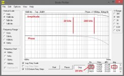
I would not like to have a nearly 1MHz bandwidth (and all the problems related to it) in an audio amplifier. What I would like to have are 2 things:
1) High enough slew rate;
2) Minimal, or at least as constant as possible, phase shift within the audio bandwidth (let say 20Hz - 20 kHz).
But those things (bandwidth, slew rate, phase characteristic) are pretty much inter-related. So I have to deal with the wide bandwidth in order to reach the desired slew rate and phase shift, despite the fact that I don't like to.
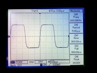
In my recent design I have reached highly linear phase shift, showing less than -3 degrees @ 20kHz. And rise/fall time 360nS while handling a fast front. Both are measured at live prototype (not simulated).
Sure, this is more an experiment, trying to understand if these things improve the audible quality.
From what I see (hear) so far, it does. The sound is incredibly natural.
It's always a compromise.
I would not like to have a nearly 1MHz bandwidth (and all the problems related to it) in an audio amplifier. What I would like to have are 2 things:
1) High enough slew rate;
2) Minimal, or at least as constant as possible, phase shift within the audio bandwidth (let say 20Hz - 20 kHz).
But those things (bandwidth, slew rate, phase characteristic) are pretty much inter-related. So I have to deal with the wide bandwidth in order to reach the desired slew rate and phase shift, despite the fact that I don't like to.
In my recent design I have reached highly linear phase shift, showing less than -3 degrees @ 20kHz. And rise/fall time 360nS while handling a fast front. Both are measured at live prototype (not simulated).
Sure, this is more an experiment, trying to understand if these things improve the audible quality.
From what I see (hear) so far, it does. The sound is incredibly natural.
Attachments
Last edited:
- Home
- Amplifiers
- Solid State
- CFA Topology Audio Amplifiers