The sound of Current Feedback--Most (but not all) "sound like" a sort of very mild "noise gate" or wonderful rest, in-between the notes, which helps the ear, because the ear is maximally sensitive at comparisons.
Also, your square wave test looks like slight overcompensation, which is favorable for a highly palatable tone, but it might could image better/bigger if you squared that up some.
The higher speed capacity amplifier, also requiring low capacitance devices, tends to make a no-grit treble, which seems like (and probably is) higher resolution--that opportunity exists.
Last edited:
The sound of Current Feedback--Most (but not all) "sound like" a sort of very mild "noise gate" or wonderful rest, in-between the notes, which helps the ear, because the ear is maximally sensitive at comparisons.
Also, your square wave test looks like slight overcompensation, which is favorable for a highly palatable tone, but it might could image better/bigger if you squared that up some.
.
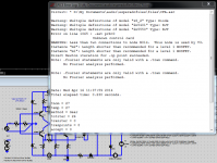
It's a 200kHz square wave for heaven's sake! I really don't see why anyone of sound mind would want to square up the edges of that even more.
It's a 200kHz square wave for heaven's sake! I really don't see why anyone of sound mind would want to square up the edges of that even more.
Exactly 🙂 At 20 kHz and below it looks simply ideal. That was the point of going that far...
Less PSRR at low frequencies than LTP based amps. But better at very HF, due to their bandwidth.Well... Just recently realized that power supply for CFA requires much more attention.
http://www.esperado.fr/temp/VSSA/vssa-vs-vfa.html
A solution to improve this point can be to add a little cap multiplier on the rails before to feed voltage amplifier and input stages.
For OPS, a solution i know to work on most of the amps is to add a 470µF (top quality) near it, paralleled with 47, 4.7 Lytics & 0.47µFfilm caps. And, as said kgrlee, the same between the rails.
Big caps near the PSU (i prefer a mono bloc for a stereo amplifier).
About compensation, i use the following method: Try to get the max flat response without overshoot at HF with the comp, then add a filter in the input to kill any overshoot (you can filter here at a lot lower frequency with benefits).
Last edited:
Manso,
That is an interesting design you just posted. Can you tell us something about it for us laymen? It looks very different than what I have seen, I'm not sure I can follow all that is going on there. Just a brief description of how that topology is working would be nice.
I was hoping Scott Wurcer would come say some about it but anyway its designed and patented by Roy Gosser from Analog Devices. That man is a genius when it comes to analog design, he has many more patents to his name. Im 99 % sure its the circuit inside the AD811 and AD812 CFA opamps, the so called 2 stage CFA as it has a second gainstage.
Nevermind the little printing errors, the circuit works and can be simplified some when you dont need precision offsets. I have working amp based on it. What you gain is extra loop gain, similar to VFA so with it one can attain higher feedback factors like VFA which translates to lower THD compaired to the standard CFA designs you see posted here. Bandwith as well as slew is also enhanced. Its possible to further linearize the circuit but really not neccessary.
Although old by todays standard many including me praise the sonic attributes of these opamps.
Ill post the patent number, better you follow Gosser s description of the circuit or semantic war might break out again.
Is that without AFEC engaged 😱
That's with AFEC engaged.
The point is you can take an exceedingly simple CFA circuit like the nx-Amp (no cascode on front end diamond buffer, no beta enhanced or cascoded TIS and a simple EF2) scale it up to >400W and get very good distortion results - ok, it is a sim granted. PSRR also better than with cap multipliers and you can retain the wide bandwidth and hi SR of the main power amp stage.
If you want sub ppm distortion, cascode the front end, use a beta enhancer, go EF3 and use TPC/TMC. You could conceivably drop the beta enhancer and still get to 1 ppm - but I think the addional effort is not worth it - you will not hear the diff between 20 ppm and 1 ppm.
For a 2.5 ppm at 400 W 20 kHz, I posted a circuit earlier on in this thread - but that was not using AFEC IIRC.
Last edited:
Less PSRR at low frequencies than LTP based amps. But better at very HF, due to their bandwidth.
http://www.esperado.fr/temp/VSSA/vssa-vs-vfa.html
I pointed out that these sims are relying on models that you aren't linking properly for clean LTspice installations, have circuit probelms
http://www.diyaudio.com/forums/solid-state/218689-cfb-topology-superior-why-20.html#post3207545
you still don't have it right - this computer is only a month old - so my LTspice is new, no mods to its libs
Attachments
Last edited:
Well... Just recently realized that power supply for CFA requires much more attention.
Wide bandwidth, high currents...
I've got +/-24V regulated supply for the input buffer and +/-52V unregulated (33'000 uF in each shoulder) for the power section.
Looked at the rails. See ~50mv p-p oscillation @ 97.15 MHz (!) at +/-24V.
And lots of different garbage at +/-52V, of course increasing with higher loads.
Though the signal at the amp output looks fine.
This does not sound right. Oscillation at ~100 MHz sounds like you have a problem inside your amp.
I had 800 mV pk ~pk 180 MHz on a VFA LTP cascode. I could not see anything wrong on the output. The cure was to aff base stoppers to the cascode.
Oscillation at these freqs will often propagate all over the board and can be difficult to track down.
Another one to watch are EF3's - see Bob Coredell for the low down on how to deal with it - I've used his techniques and they work very well eg on my e-Amp design.
Agree. This is more an overall engineering question, than CFA- or VFA- or whatever-FA related. Couple of comments though.
Sure, this is more an experiment, trying to understand if these things improve the audible quality.
From what I see (hear) so far, it does. The sound is incredibly natural.
Still, the same results as it is world-wide. Amazing. - Extreamly natural sounding.
😎🙂
THx-RNMarsh
Yeah, those LFET models are bad, they aren't the right format for LTSpice. Use Cordell's K1056/J162 models.
That's with AFEC engaged.
The point is you can take an exceedingly simple CFA circuit like the nx-Amp (no cascode on front end diamond buffer, no beta enhanced or cascoded TIS and a simple EF2) scale it up to >400W and get very good distortion results - ok, it is a sim granted. PSRR also better than with cap multipliers and you can retain the wide bandwidth and hi SR of the main power amp stage.
If you want sub ppm distortion, cascode the front end, use a beta enhancer, go EF3 and use TPC/TMC. You could conceivably drop the beta enhancer and still get to 1 ppm - but I think the addional effort is not worth it - you will not hear the diff between 20 ppm and 1 ppm.
For a 2.5 ppm at 400 W 20 kHz, I posted a circuit earlier on in this thread - but that was not using AFEC IIRC.
Cascoding the front end brings no THD improvement, thats not the reason for its use. Without beta enhancer, 1ppm, you should seriously re examine your trust in sims.
Even if you can't see oscillation, you'll find that THD becomes (often much) worse on certain loads .. if you leave out the electrolytics. The physical size of the caps is important.
The reduction in THD has to do with load-dependent rail noises which leak into the output through PSRR. They may be dominant or they may be swamped by the amplifier's distortion. I would try to improve PSRR before going for expensive caps.
I pointed out that these sims are relying on models that you aren't linking properly for clean LTspice installations, have circuit probelms
http://www.diyaudio.com/forums/solid-state/218689-cfb-topology-superior-why-20.html#post3207545
you still don't have it right - this computer is only a month old - so my LTspice is new, no mods to its libs
I wish i could contribute more via freeware LTSpice. But, I dont use it. Does anyone here besides myself and Doug Self use Spectrum's Micro-Cap 10 SW??
-RNM
Last edited:
The reduction in THD has to do with load-dependent rail noises which leak into the output through PSRR. They may be dominant or they may be swamped by the amplifier's distortion. I would try to improve PSRR before going for expensive caps.
First -- is it differential-mode noise or Common-mode noise on the rails?
THx-RNMarsh
One added stage ? It means one pole more, how can Bandwidth and slew rate can be enhanced, once compensated ?Bandwith as well as slew is also enhanced.
One added stage ? It means one pole more, how can Bandwidth and slew rate can be enhanced, once compensated ?
Sometimes the added stage IS the compensation, which reduces the pole of the preceeding or proceeding stage.
First -- is it differential-mode noise or Common-mode noise on the rails?
THx-RNMarsh
I call them noises but they are half-sine components of the load current causing voltage across the rail impedance. So it's technically DM noise, and is reduced by better DM filtering, IE lower rail impedance.
Repeat & Rinse
Hey kids, i'm no expert, as you're probably aware 😀 just know some stuff ! But, a lot of what keeps getting posted over n over is, i would have thought, things have been known for decades.
For eg, i've mentioned several times before, in different threads, about Dennis Morecrofts DNA gear. He built/builds using INDIVIDUAL returns to the Star point, for EACH component that requires a common connection. He's been doing this since @ least the early 1980's !
Try it & see 😉
Oscillation at ~100 MHz sounds like you have a problem inside your amp.
Yep, trying to find the source, though it is radio-transmitting all over the line amp board (low level, but still).
Another one to watch are EF3's - see Bob Coredell for the low down on how to deal with it - I've used his techniques and they work very well eg on my e-Amp design.
Thank you for this - I will look closer into it.
Still thinking about at least additional RC @ the OP rails...
Hey kids, i'm no expert, as you're probably aware 😀 just know some stuff ! But, a lot of what keeps getting posted over n over is, i would have thought, things have been known for decades.
For eg, i've mentioned several times before, in different threads, about Dennis Morecrofts DNA gear. He built/builds using INDIVIDUAL returns to the Star point, for EACH component that requires a common connection. He's been doing this since @ least the early 1980's !
Try it & see 😉
Yes, since shortly after 1983. Everyone was about 30 years younger then. Unfortuantely, not everyone here read TAA magazine (now owned by Elecktor). Those doing amp design read it and applied what they read.
I wrote an article (7/'83) called "Power Up. An Overview of Power Supply Considerations"
excerpt --
View attachment Current phase.pdf
THx-RNMarsh
Last edited:
- Home
- Amplifiers
- Solid State
- CFA Topology Audio Amplifiers