There is a thread on this. Not pretty 😉
Jan
I saw one thread on this but it didn't go anywhere. If it were given the kind of attention this thread has had them maybe...
I not talking about converting voltage amplifiers to do the job. What I'm proposing is to start from the ground up and do it right. No pun intended. It's not a new concept and it has been done successfully before, Hawksford and company published a paper on this years ago and the F1 is another example. We can probably do better than 5% disto though.
Apart the name 'Current feedback', a CFA is ... a voltage amplifier.It seems like a natural progression from current feedback. Why not a current amplifier from input to output. A large variable current source/sink. Operate the speaker in a series connection in a current loop rather than a voltage loop. After all a speaker is a current controlled device.
If you like to play with current amplifiers to drive speakers, good luck. I don't know any speaker designed to be driven in current. It is the typical "false good idea" that everyone has had at one time or another, and given-it up.
Last edited:
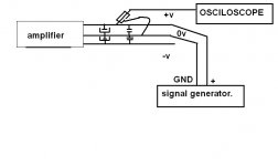
This is how I do it: Just take an amp you have sitting around with both film decoupling and large reservoirs on the board, drain the reservoirs, and inject a square wave from a signal generator across the rails. The circuit doesn't need to be on for you to observe the resonance. Just don't send DC into the input of your signal generator. Probe across the rails with your oscilloscope and watch the ringing. You may have to turn the signal generator voltage up to get a clear trace. I used 10V with a 50R output impedance which is 200mA. I also used the offset voltage function to check if the ringing changed with some bias voltage - maybe slightly.
I did this with a TDA7297 kit gifted to me by a friend. It came with a 5mm 100nF decoupler and a 2200u reservoir. The resonance was 3.3MHz. I damped that and sibilance decreased. I replaced the cap with a 5mm 1u decoupler on the same pad, so inductance was the same, and then damped that with a 100V/47u Nichicon VR (it was the junk cap that worked based on measurements). I have another chipamp I damped with 50V 4.7uF caps; it had 5mm 100nF film decouplers and long traces (inductors) between them and the 220uF reservoirs.
Sorry my English isn't good
Do you mean something like this?
Regards.
Thimios.
Attachments
Last edited:
Thanks.🙂Yep! 🙂
I have a question about frequency setting ,can you give more datails?
Last edited:
I came across this web page on search for current drive amplifiers.
Amplifier topologies for current-drive | Current-Drive - The Natural Way of Loudspeaker Operation
It seems like a natural progression from current feedback. Why not a current amplifier from input to output. A large variable current source/sink. Operate the speaker in a series connection in a current loop rather than a voltage loop. After all a speaker is a current controlled device. This probably deserves a thread of its own.
You can find out more in a published book -- "Current-driving of Loudspeakers" By Esa Merilainen. First Edition 2010. 342 pages. Current-Drive - The Natural Way of Loudspeaker Operation "Eliminating Major Distortion and Interference Effects by the Physically Correct Operation Method."
THx-RNMarsh
Last edited:
As far as the current-drive stuff goes, someone could just DO it and make it available to DIYers, because they keep asking about it. I'm curious too, just haven't gotten around to trying it out.
Maybe OS would be willing to adapt one of his designs to current drive?
Maybe OS would be willing to adapt one of his designs to current drive?
You can find out more in a published book -- "Current-driving of Loudspeakers" By Esa Merilainen. First Edition 2010. 342 pages. Current-Drive - The Natural Way of Loudspeaker Operation "Eliminating Major Distortion and Interference Effects by the Physically Correct Operation Method."
THx-RNMarsh
Yes. That's what I linked too.
Nelson Pass has a paper on his web site. Designing crossovers for current drive or something like that. The usual filters won't work. Speaker and amplifier have to integrated together.
A voltage amplifier converted to current drive will oscillate. Compensation is different for current drive.
Hi Dave,
I have the book. It is quit interesting. Includes working circuits and even a 1:1 pcb layout for one of the circuits. The section on measurement techniques includes a circuit for an --- EMF extractor.
THx-RNMarsh
Thanks.🙂
I have a question about frequency setting ,can you give more datails?
I usually end up around 200KHz when I'm looking at square waves.
What I wonder though is whether these resonances ever occur in the typical audio power supply.
Jan
Absolutely. How do you put an inductor and capacitor in a loop without damping and NOT get a resonator? It can and does happen all the time. Now if the only caps on your board are a 22uF lytic and a 1uF film cap, then the film will probably be damped well, and I've seen boards like this, but usually people put reservoirs very close to the amp and this is what closes a low-resistance inductive loop through the film cap.
As far as the current-drive stuff goes, someone could just DO it and make it available to DIYers, because they keep asking about it. I'm curious too, just haven't gotten around to trying it out. . . .

Unfortunately there's resistance at the groundside of the feedback-shunt RC. Problem: the cap isn't at ground. So, the ESR is increased by 1k to simulate the worst cap ever and the inv input base stopper is now a capacitor which is not preferable. Tis backwards. If the treble droop wasn't on purpose, then how do we do current drive with the cap at ground?
Last edited:
Dan, it doesn't matter whether the cap is before or after the resistor, it's the same because they are in series. The same current flows through both. The only problem might be static interference picked up by the large surface area of the cap, which does not see a short to ground like it would if one side were grounded.
Unfortunately there's resistance at the groundside of the feedback-shunt RC. Problem: the cap isn't at ground. So, the ESR is increased by 1k to simulate the worst cap ever and the inv input base stopper is now a capacitor which is not preferable. Tis backwards. If the treble droop wasn't on purpose, then how do we do current drive with the cap at ground?
I placed the cap right on the shunt and then mixed a ratio of voltage and current feedback.
Works much better that way. With the right ratio of Vf and Cf to obtain an output impedance equal to the speaker dcr one gets a 'maximum power transfer' curve.
That's like saying you get more power by putting an 8R resistor in series with a speaker. In this case you're emulating an 8R resistor with the amplifier, so the amplifier is dissipating the energy rather than the resistor. But the effect is the same. In my understanding the efficiency is highest when the amplifier's output impedance is either much higher or much lower than the speaker's.
Also I seem to recall Esa said that the amplifier output impedance needed to be more than 1k or so, something relatively high, to get most of the benefit of current drive.
Also I seem to recall Esa said that the amplifier output impedance needed to be more than 1k or so, something relatively high, to get most of the benefit of current drive.
Thanks again ,i will try this.I usually end up around 200KHz when I'm looking at square waves.
Best regards.
Thimios
The maximum power transfer theorem.
https://www.princeton.edu/~achaney/tmve/wiki100k/docs/Maximum_power_theorem.html
When the source impedance is roughly that of the load impedance the power transfer is at maximum, top of the curve. If the source impedance is lower than the load then it's more efficient.
https://www.princeton.edu/~achaney/tmve/wiki100k/docs/Maximum_power_theorem.html
When the source impedance is roughly that of the load impedance the power transfer is at maximum, top of the curve. If the source impedance is lower than the load then it's more efficient.
I placed the cap right on the shunt and then mixed a ratio of voltage and current feedback.
Works much better that way. With the right ratio of Vf and Cf to obtain an output impedance equal to the speaker dcr one gets a 'maximum power transfer' curve.
Thanks David!
But I couldn't interpret the words into circuits. Got schema or sketch? And some advices on adjustments?
Last edited:
Is this current driven speaker (old sea snake) question has something to do in this CFA thread ?
Is this current driven speaker (old sea snake) question has something to do in this CFA thread ?
Agree, its completly offtopic as is all the noise about caps.
Lets get back to CFA.
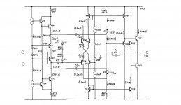
Anyone tried any enhanched type CFA topologies ?? So far only bog standard stuff has been shown.
How about this ?? , Scott should recognise this.
Attachments
Last edited:
- Home
- Amplifiers
- Solid State
- CFA Topology Audio Amplifiers