share pcb
Hi.
form link http://www.diyaudio.com/forums/atta...396681443-no-nfb-line-amp-gainwire-mk2-01.jpg
you can shared pcb board dirve and power output board or file p-cad
i will built it.
Thank you.
Hi All,
Greetings from Lithuania. I travel around Europe till the next Saturday, so testing will be on hold till I'm back to Moscow, though I will run some useful simulations 😉
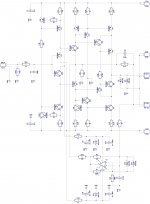
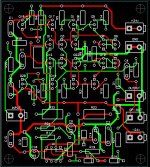
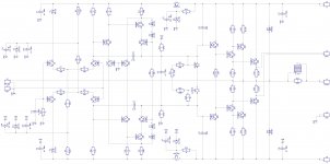
For those who are interested, attached is a final schematic of Damir's line amp section, as I use it in my power amp, as well as corresponding PCB layout (in PDF).
I can share pcb in P-CAD ASCII, Gerber - just let me know what format is good for you.
Cheers,
Valery
Hi.
form link http://www.diyaudio.com/forums/atta...396681443-no-nfb-line-amp-gainwire-mk2-01.jpg
you can shared pcb board dirve and power output board or file p-cad
i will built it.
Thank you.
PCB
Hi sa155, here we go - attached are final schematics (jpg) and PCBs (jpg + P-CAD ASCII).
Let me know if you have questions, etc.
BR,
Valery
Hi.
form link http://www.diyaudio.com/forums/atta...396681443-no-nfb-line-amp-gainwire-mk2-01.jpg
you can shared pcb board dirve and power output board or file p-cad
i will built it.
Thank you.
Hi sa155, here we go - attached are final schematics (jpg) and PCBs (jpg + P-CAD ASCII).
Let me know if you have questions, etc.
BR,
Valery
Attachments

You're welcome. This version of the power section is adjusted for +/- 52V DC rails. If you want +/- 80V or something in between - let me know, some values need to be corrected.
Keep us posted on the pogress - very interesting! 😉
Cheers,
Valery
I did some more listening, and I like it each time more and more.
I am very interested in others listening opinion, but for the moment only one presented here.
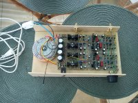
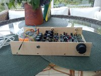
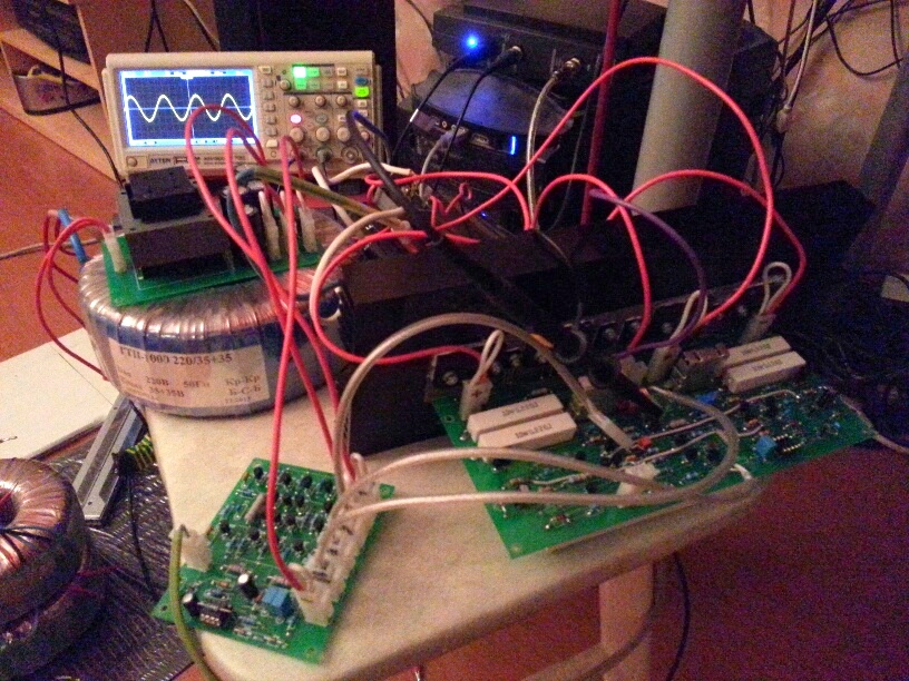
This is my temporary housing for the pre amp, you can see ordinary wires used with no special attention to the wiring, but still it is dead quiet. Even the step attenuator I used shows no weakness.
BR Damir
I am very interested in others listening opinion, but for the moment only one presented here.
This is my temporary housing for the pre amp, you can see ordinary wires used with no special attention to the wiring, but still it is dead quiet. Even the step attenuator I used shows no weakness.
BR Damir
Attachments
Last edited:
I did some more listening, and I like it each time more and more.
I am very interested in others listening opinion, but for the moment only one presented here.
This is my temporary housing for the pre amp, you can see ordinary wires used with no special attention to the wiring, but still it is dead quit. Even the step attenuator I used shows no weakness.
BR Damir
Are those Panasonic FM that you used ?? Preferred capacitors ??
In a couple more weeks Ill have time to build a sample for me.
Are those Panasonic FM that you used ?? Preferred capacitors ??
In a couple more weeks Ill have time to build a sample for me.
All electrolytic caps are Panasonic FC type here. I don't have enough experience with different capacitors to have preferred ones, I use Panasonic, Muse, Elna(silmic)..
What are your preferred caps?
You have PM.
Damir
Panasonic FC is what our designs recommend although I have had some good results with FM which is the reason I asked about those. Usually one sees designs where a smaller cap is parralelled with the electrolytics but there is no need with these as their impedance is low at high frequencies. Also the parralelling can create problems. I find caps do sound different, these panasonics (FC, FM) and the Muse series in that order are my prefered caps.
I will also be using PRP resistors ( series Pr9372) for the build.
I will also be using PRP resistors ( series Pr9372) for the build.
version +/- 80v
Hi. vzaichenko
again for request please post version +/- 80v
thank you.
You're welcome. This version of the power section is adjusted for +/- 52V DC rails. If you want +/- 80V or something in between - let me know, some values need to be corrected.
Keep us posted on the pogress - very interesting! 😉
Cheers,
Valery
Hi. vzaichenko
again for request please post version +/- 80v
thank you.
FINAL version
Hi, sorry for delay - got back home yesterday, fine-tuned compensation.
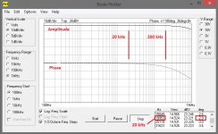
Resulting Bode plot is measured with Velleman PCSGU250 oscilloscope-generator combination. Unfortunately it can build Bode Plot only up to 1MHz 🙂
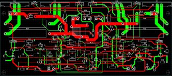
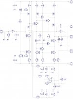
Final versions of schematics and power section PCB are attached. Previous version PCB also can be used - just C4 will have to be soldered on top of R36.
Corrected values for the buffer (GW) and for the power section (PA, +/-52V rails), as well as for +/-80V option are here:
GW v04 FINAL
C4 5.1p Changed
C7 47p Changed
R24 27k Changed
PA v04 FINAL
C4 1nF Added
C3 2.2p Changed
C5 2.2p Changed
C12 100p Changed
C13 100p Changed
C16 X Removed
C19 X Removed
PA v04 +/-80V option
R4 10k Changed
R5 10k Changed
R16 51k Changed
D9 X Removed
D10 X Removed
Square wave response is perfect, phase shift @ 20k is -2.9 deg, raise/fall time is less than 700 nS @ full amplitude.
Excellent, excellent sound. Extreme clarity. Well-controlled bass.
Auditioned SACDs of different styles at different volume levels today.
Especially like it with well-recorded jazz trios/quartets. "Effect of presence" is very strong.
GW buffer +/-24V rails are regulated (stabilized).
And make sure PSU for power section is powerful enough! 😉
NOTE! It is very important to remove C16, C19 - they are not necessary for compensation, but they slow-down the drivers, resulting in possibility of shoot-through current in OPS.
Cheers,
Valery
Hi, sorry for delay - got back home yesterday, fine-tuned compensation.
Resulting Bode plot is measured with Velleman PCSGU250 oscilloscope-generator combination. Unfortunately it can build Bode Plot only up to 1MHz 🙂
Final versions of schematics and power section PCB are attached. Previous version PCB also can be used - just C4 will have to be soldered on top of R36.
Corrected values for the buffer (GW) and for the power section (PA, +/-52V rails), as well as for +/-80V option are here:
GW v04 FINAL
C4 5.1p Changed
C7 47p Changed
R24 27k Changed
PA v04 FINAL
C4 1nF Added
C3 2.2p Changed
C5 2.2p Changed
C12 100p Changed
C13 100p Changed
C16 X Removed
C19 X Removed
PA v04 +/-80V option
R4 10k Changed
R5 10k Changed
R16 51k Changed
D9 X Removed
D10 X Removed
Square wave response is perfect, phase shift @ 20k is -2.9 deg, raise/fall time is less than 700 nS @ full amplitude.
Excellent, excellent sound. Extreme clarity. Well-controlled bass.
Auditioned SACDs of different styles at different volume levels today.
Especially like it with well-recorded jazz trios/quartets. "Effect of presence" is very strong.
GW buffer +/-24V rails are regulated (stabilized).
And make sure PSU for power section is powerful enough! 😉
NOTE! It is very important to remove C16, C19 - they are not necessary for compensation, but they slow-down the drivers, resulting in possibility of shoot-through current in OPS.
Cheers,
Valery
Attachments


Last edited:
P-CAD ASCII
I need file P-CAD ASCII too.
Thank you.
Hi, sorry for delay - got back home yesterday, fine-tuned compensation.
Resulting Bode plot is measured with Velleman PCSGU250 oscilloscope-generator combination. Unfortunately it can build Bode Plot only up to 1MHz 🙂
Final versions of schematics and power section PCB are attached. Previous version PCB also can be used - just C4 will have to be soldered on top of R36.
Corrected values for the buffer (GW) and for the power section (PA, +/-52V rails), as well as for +/-80V option are here:
GW v04 FINAL
C4 5.1p Changed
C7 47p Changed
R24 27k Changed
PA v04 FINAL
C4 1nF Added
C3 2.2p Changed
C5 2.2p Changed
C12 100p Changed
C13 100p Changed
C16 X Removed
C19 X Removed
PA v04 +/-80V option
R4 10k Changed
R5 10k Changed
R16 51k Changed
D9 X Removed
D10 X Removed
Square wave response is perfect, phase shift @ 20k is -2.9 deg, raise/fall time is less than 700 nS @ full amplitude.
Excellent, excellent sound. Extreme clarity. Well-controlled bass.
Auditioned SACDs of different styles at different volume levels today.
Especially like it with well-recorded jazz trios/quartets. "Effect of presence" is very strong.
GW buffer +/-24V rails are regulated (stabilized).
And make sure PSU for power section is powerful enough! 😉
NOTE! It is very important to remove C16, C19 - they are not necessary for compensation, but they slow-down the drivers, resulting in possibility of shoot-through current in OPS.
Cheers,
Valery
I need file P-CAD ASCII too.
Thank you.
I need file P-CAD ASCII too.
Thank you.
Oops... Attached the wrong file in the previous post.
Here it is.
Attachments
part list
Hi. Vzaichenko
I look project the best.
I will trial build this project please attach part list, oder them.
Oops... Attached the wrong file in the previous post.
Here it is.
Hi. Vzaichenko
I look project the best.
I will trial build this project please attach part list, oder them.
OK, here they are in MS Excel format.
You have to change Q12 from BC560 to BC550 in your schematic and in the BOM.
Damir
You have to change Q12 from BC560 to BC550 in your schematic and in the BOM.
Damir
Damir, thanks a lot! I can't even imagine how this could happen. Emitter arrow is correct, but the label is wrong...
Here are corrected ones.
Attachments
Damir, thanks a lot! I can't even imagine how this could happen. Emitter arrow is correct, but the label is wrong...
Here are corrected ones.
Oh this is quite OK, I am doing stupid mistake all the time(not that your mistake is stupid, mine are). This was not mistake that could confuse experienced DIYer, but could less experienced.
I know that
Q11-Q12
Q3-Q4
Q15-Q16
Q13-Q14
need Vbe matching, but with my batch BC550C and BC560C, they are all in 5% (0.565V-0.555V) range so I can pick 8 couple base on hfe that match from 0.17% to 3.94%.
So do 4 couple above have different important in matching so I can split them base on that?
Q11-Q12
Q3-Q4
Q15-Q16
Q13-Q14
need Vbe matching, but with my batch BC550C and BC560C, they are all in 5% (0.565V-0.555V) range so I can pick 8 couple base on hfe that match from 0.17% to 3.94%.
So do 4 couple above have different important in matching so I can split them base on that?
- Status
- Not open for further replies.
- Home
- Amplifiers
- Solid State
- No NFB line amp (GainWire mk2)