All these are dead silent even the CFA Gnome.
Yes , proper local star ground + lifted input = "dead silent".
Single pair bias would be ideal 60-70ma (14-15mv / .22R).
OS
Been following this thread on and off. Anyone tried these front ends with Bob Cordell's version of the Hawksford Error Corrected OPS?
It is low cost and in my experience sounds very nice.
It is low cost and in my experience sounds very nice.
It is important to understand, that servo is replacing not a trimpot, but a guy, sitting in front of it with a screwdriver, looking at the V-meter and adjusting it constantly 🙂 Trimpot is static, servo is dynamic.
My practical measurements show the following (same amp):
- DC servo off - output offset fluctuates slowly in the range +/- 70mV;
- DC servo on - output offset fluctuates in the range +/- 0.1mV.
BTW, why except CFA with diamond buffer?
The above example is actually the one with diamond buffer.
Hmmm..., I must learn again about servo.
I sim the CFA with diamond buffer with various type of transistor combinations on diamond buffer and IPS. It hard to optimize AC performance and DC performance without servo.
Been following this thread on and off. Anyone tried these front ends with Bob Cordell's version of the Hawksford Error Corrected OPS?
It is low cost and in my experience sounds very nice.
Can you share the schematic of your implementation?
bob cordell would likely point you to his website for the schematic:
CordellAudio.com - A MOSFET Power Amplifier with Error Correction
his front end and some updated versions of it that he has posted on this site are also high slew rate designs. i would also be curious about the reverse of poster mcd99uk's question: how about one of bob's front ends on the generic output triple the OS has provided?
mlloyd1
Can you share the schematic of your implementation?
Been down that road ....
The "symasui" is Bob's front end. Minus the second differential stage .....
VAS is very similar with the cascode /enhanced CM.
Using lag compensation and the second stage LTP ....
-2-5ppm
-80+db CLG at LF
-harder to compensate/device dependent/prone to oscillate unless
you "get it right".
-18 devices
My "simpler" "pitchfork villager" version -
5-30 ppm (thd 1K/20K - up to 120V p-p)
- only 68-72db LF CLG
- real easy both to initially compensate and the ability to enhance
compensation while remaining rock solid.
- ANY device remains stable within limits (Re choice.
-simple 12 device DIY friendly.
I do not believe the extra 6 devices will result in a better
sounding-performing amp (besides the "mine is lower" PPM thing ).
OS
bob cordell would likely point you to his website for the schematic:
CordellAudio.com - A MOSFET Power Amplifier with Error Correction
his front end and some updated versions of it that he has posted on this site are also high slew rate designs. i would also be curious about the reverse of poster mcd99uk's question: how about one of bob's front ends on the generic output triple the OS has provided?
mlloyd1
The "symasui" is Bob's front end. Minus the second differential stage .....
VAS is very similar with the cascode /enhanced CM.
Using lag compensation and the second stage LTP ....
-2-5ppm
-80+db CLG at LF
-harder to compensate/device dependent/prone to oscillate unless
you "get it right".
-18 devices
My "simpler" "pitchfork villager" version -
5-30 ppm (thd 1K/20K - up to 120V p-p)
- only 68-72db LF CLG
- real easy both to initially compensate and the ability to enhance
compensation while remaining rock solid.
- ANY device remains stable within limits (Re choice.
-simple 12 device DIY friendly.
I do not believe the extra 6 devices will result in a better
sounding-performing amp (besides the "mine is lower" PPM thing ).
OS
bob cordell would likely point you to his website for the schematic:
CordellAudio.com - A MOSFET Power Amplifier with Error Correction
mlloyd1
This would be the output stage. 🙂
Although, it appears to work better and easier to keep stable with cascoded drivers. This way you can use smaller devices for the MOSFET drivers. Even TO92 (BC5x0c) devices work well in my limited experience.
One of the criteria I have for my designs is cost. My first amp project cost a small fortune and wasn't very successful. It worked but not as well as expected. The Cordell HEC does not need any fancy components and is still cost effective at higher powers. Ticks some of the necessary boxes.
Don't want to derail this thread in any way shape or form, just thought that the Cordell HEC could be a worthwhile addition to the options.
Paul
Yes , another output stage .
As well as one that does error correction - I WANT one that is non- switching.
No bloated 20 component deal either.
I have seen a Japanese amp that does both with one dual op-amp.
(controlling a standard BJT EF3).
Another "evil op-amp" 😱 ....
I suppose this design will not receive a blessing. 😀
OS
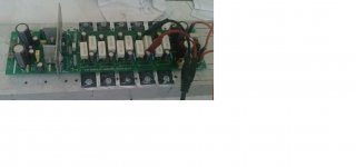
My 5 pairs emitter follower and the complete version.
The IPS is simple VSSA with single VAS transistor.
Listening result:
It is best of amp that I ever built. Better than my VSSA variant 😎. I am using +-63V power supply.
My first CFA with Hawksford cascode is slightly worse in high frequency than my VSSA variant. May be I can not optimize it, not yet.
Now I can make thread on headsink using tap 😀.
Attachments

My first CFA with Hawksford cascode is slightly worse in high frequency than my VSSA variant.
The same with others.

Listening result:My 5 pairs emitter follower and the complete version.
The IPS is simple VSSA with single VAS transistor.
Listening result:
It is best of amp that I ever built. Better than my VSSA variant 😎. I am using +-63V power supply.
My first CFA with Hawksford cascode is slightly worse in high frequency than my VSSA variant. May be I can not optimize it, not yet.
Now I can make thread on headsink using tap 😀.
It is best of amp that I ever built. Better than my VSSA variant 😎. I am using +-63V power supply.
Good news Bimo,i will try this CFA-X soon ,as i have this pcb already.
Yes , another output stage .
As well as one that does error correction - I WANT one that is non- switching.
No bloated 20 component deal either.
I have seen a Japanese amp that does both with one dual op-amp.
(controlling a standard BJT EF3).
Another "evil op-amp" 😱 ....
I suppose this design will not receive a blessing. 😀
OS
Personally, I'm after an OPS that does error correction and is non switching / auto biased. Aware that Edmond Stewart has a scheme on his site, maybe there are other alternatives worth viewing.
This op amp controlled EF3 sounds interesting. Nothing evil about op amps IMHO. Any chance of a link please? Like to have a look at it. Maybe it holds some interesting ideas.
Blessings are expensive things... 😉
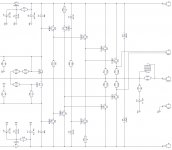
Drivers with CCS load
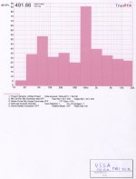
I have practically tested the OP with class A drivers (loaded with CCSs) within VFA design (see attached OP schematic and overall spectrum).
Sounds very good. I mean - it doesn't sound. Ultra-linear 😉
+/- 80V DC
I have practically tested the OP with class A drivers (loaded with CCSs) within VFA design (see attached OP schematic and overall spectrum).
Sounds very good. I mean - it doesn't sound. Ultra-linear 😉
+/- 80V DC
Attachments

Last edited:
My 5 pairs emitter follower and the complete version.
The IPS is simple VSSA with single VAS transistor.
Listening result:
It is best of amp that I ever built. Better than my VSSA variant 😎. I am using +-63V power supply.
My first CFA with Hawksford cascode is slightly worse in high frequency than my VSSA variant. May be I can not optimize it, not yet.
Now I can make thread on headsink using tap 😀.
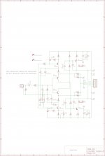
The simulation result using 3 pairs triple emitter follower at +-70VDC:
Phase Margin = 69
Gain Margin = 9
Slew Rate = 400 V/uS
THD 228Watt rms/8Ohm, 1KHz -> 0.000823%
THD 228Watt rms/8 Ohm, 20KHz -> 0.004953%
Edit: I use some components from my 3 pairs triple emitter follower and from my junk box 😀
Last edited:
hi bimo, what version of simple VSSA are you using in IPS, is this the CFA-X v1.2? thanks
I use my own design. I only follow Ostripper's OPS design with same contruction but different compensation. Now I run the pre-driver transistor hotter than Ostripper design.
The modular design fit to my need. I want to learn to design audio amplifier.
Dear bimo.
Could you introduce all your IPS module, that allowed you to get the best sound.
Here it is.
Attachments


- Home
- Amplifiers
- Solid State
- Slewmaster - CFA vs. VFA "Rumble"