It's a VFA ! Lead comp + dc blocker are relegated to the IC. The quality
of the full amp will be determined by the topology of the IC.
As a reference the TL072 is a "blameless" with fet inputs , the NE5532
is a symasym ... etc...
Thanks ..... it is done (I will get it .. now)
OS
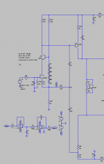
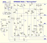
Yes, it's no doubt a VFA.
By the way, Q28 is shown the wrong way. It is PNP - the arrow must be opposite direction. Very "robust" design. BTW, feedback through R28, R29 slightly compensated with C16, C17 is a local current feedback.
OS, keep in mind ,I can solder smd devices very well,no need of aduptors😉I'm not "ditching" the CFA.
I will succeed in making the diamond CFA better than the "VSSA".
On the VFA side , the spook and the symasui will be refined to
audiophile quality. This MUST be ... no more "childs play".
DIY must be brought to a proper compromise. (no more toys -projects)
Builds that your grandchildren will recap. 😀
OS
Thimios
Last edited:
OS, there was an amplifier with an op amp front end that showed on this forum a few years back. It was by Jan Dupont. He called it the Lynx. Some builders complained of problems when they swapped op amps (go figure...) . The build thread can be found by doing a forum search.
Jan Dupont's builder's guide can be found here: http://www.audio-circuit.dk/images/LYNX-v3-0-QAG.pdf
And to invite conversation I have uploaded the schematic here:
Jan Dupont's builder's guide can be found here: http://www.audio-circuit.dk/images/LYNX-v3-0-QAG.pdf
And to invite conversation I have uploaded the schematic here:
Attachments
Carl,
I don't see any problem with using an opamp in the input of a power amp, why not, we are using those eight legged devices to operate the servo circuit. The problems come in when as you say people start changing the opamp without any regard to the fact that a circuit could be optimized, should be optimized for that exact opamp. I see this all the time in threads where people are just rolling the opamps and trying to say that one sounds better than another without changing the circuit to match the opamp they have chosen. It make no sense to me to do that.
Reminds me of how people just change the size of wheels and tires on a car to different heights, profiles and do not consider how that changes the needed spring rate. Really lame in my eyes.
Is there some inherent reason that the cfa amplifiers need to be these symmetric topologies or is that just a way to improve the final outcome? Aren't there none symmetric topologies that are still called cfa amplifiers?
Dear lovers of good sound.
Probably, everyone interested to choose for themselves a better sounding amp.
Very important to share the results of comparative listening.
I want to share the results of comparing the sound options 4x voltage amplifiers .
Tired of listening to amplifiers Prototyping housing and as a constructor I bought Pioneer A- 30. Attracted a lot of looks and functions. Sound Pioneer A- 30 mode «direct» do not like and not much interested as planned improvements.
Next in order of numbers arranged my personal preference .
Were manufactured board voltage amplifiers ( 2.3.4) and listened .
For Pioneer A- 30 was amended . If you listen without comparing - all amplifiers sound good . But when comparing the best helpful Pioneer A- 30 after the changes. Changes occur after the scheme.
For a final decision by each amplifier were heard 4 test drive composed expert in good and proper sound nick Prophetmaster. Feature selected tracks - as through a magnifying glass shows the possibility of the entire system .
conclusions :
All amplifiers sound good , but each in his own way.
1. Pioneer A30 - precise and pleasant transfer all the songs .
2 . Natalie AB - refined and intelligent sound. In my opinion, somewhat lacking sharpness
( stiffness ) .
3 . As if all is well but the soul is to Pioneer A- 30
4 . Transfer tonal balance did not like. As if not enough low frequencies compared with 1 and 3
In an attachment scheme
Attachments
Gnome,isn't dead yet even if OS believes so. This statement will make you either happy or not.
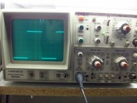
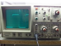
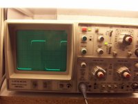
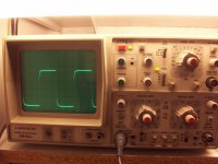
A new test changes everything .
1)1KHz
2)10KHz
3)20KHz
4)50KHz.
More datails and a surprise tomorrow.
A new test changes everything .
1)1KHz
2)10KHz
3)20KHz
4)50KHz.
More datails and a surprise tomorrow.
Attachments
Last edited:
Thanks again thimios.
It is nice that you have not given up and have made whatever changes you found necessary. I still think the answers will be found in the listening tests and not the theoretical superiority of one circuit to another by numbers alone. It will come down to the music and nothing more in the end. A great amplifier that takes the soul out of the music just won't do, it has to sound like live music if at all possible and not cold and sterile. Great work again.
It is nice that you have not given up and have made whatever changes you found necessary. I still think the answers will be found in the listening tests and not the theoretical superiority of one circuit to another by numbers alone. It will come down to the music and nothing more in the end. A great amplifier that takes the soul out of the music just won't do, it has to sound like live music if at all possible and not cold and sterile. Great work again.
Tomorrow will be a good day for you my friend, I PROMISE.🙂Thanks again thimios.
It is nice that you have not given up and have made whatever changes you found necessary. I still think the answers will be found in the listening tests and not the theoretical superiority of one circuit to another by numbers alone. It will come down to the music and nothing more in the end. A great amplifier that takes the soul out of the music just won't do, it has to sound like live music if at all possible and not cold and sterile. Great work again.
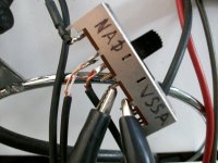
I will show an easy and simple way to compare(listening) two or more amplifiers simultaneously
Last edited:
I will be back from the jungles to the mountains in Northern California tomorrow and will look for your promise. Sounds very interesting.
THx RNMarsh
THx RNMarsh
Gnome,isn't dead yet even if OS believes so. This statement will make you either happy or not.
A new test changes everything .
1)1KHz
2)10KHz
3)20KHz
4)50KHz.
More datails and a surprise tomorrow.
Looks good , can't wait to learn more ...😱 🙁 .
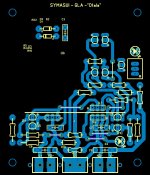
I've been doing the symasui (below)... layout is tough (3 stages and a servo).
I will do a "deluxe" version of it.
Gnome gave me depression 🙁 .
OS
Attachments
First ,i must say that testing isn't so simple and not without any risk.Looks good , can't wait to learn more ...😱 🙁 .
I've been doing the symasui (below)... layout is tough (3 stages and a servo).
I will do a "deluxe" version of it.
Gnome gave me depression 🙁 .
OS
Now i have 2 pairs of burned mjw 21195,6.
Last test was done with a couple of a1943,c5200.This time the provision of measurement instrumentation changed again.
Function generator powered via 1:1 safety tran. and osciloscope direct on the outlet(live).
This way the grounding of the oscilloscope probe can be connected to the grounding of the amplifier, the question is, at what point must log?
Up to now leave the probe ground unconnected, because the generator and the oscilloscope connected via common safety ground.
But now I had the choice to connect the grounding of promp.When probe gnd connected to the load observed oscillations. Try connect the probe gnd on Star gnd, all ok.
All?
Except a strange pulse,this disappears connecting Star gnd to Safety gnd.
This provision I had implement before burning MJW 21195,6
So the question remains, why the amplifier oscillates with MJW? Was the cause of the transistor specifically, Or is it because we had two parallel transistors?
PS Last test is with 33pf on predrivers.
Last edited:
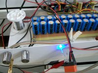
Coming soon.
It's a LISTENING test!
Not measurements only!
It's a LISTENING test!
Not measurements only!
Attachments

Last edited:
Thimios,
You need to put blinders on and change the switch blind. Just kidding, others would complain that the switch is causing sonic problems, just listen and tell us what you think.
You need to put blinders on and change the switch blind. Just kidding, others would complain that the switch is causing sonic problems, just listen and tell us what you think.
All OK ? 🙂
Perhaps the CFA's greater bandwidth makes it more susceptible to groundloops/
RFI ?
All will be well with a case and grounded heatsinks , I had a "blameless" that
became "squirrly" (misbehaved)... until I grounded all the hardware.
Wires all over the bench have a tendency to become antenna's. 😱
PS - "symasui" is coming along ... slow but sure !
Check the final circuit ... "embellished" 😀
OS
Attachments
Waiting for this!All OK ? 🙂
Perhaps the CFA's greater bandwidth makes it more susceptible to groundloops/
RFI ?
All will be well with a case and grounded heatsinks , I had a "blameless" that
became "squirrly" (misbehaved)... until I grounded all the hardware.
Wires all over the bench have a tendency to become antenna's. 😱
PS - "symasui" is coming along ... slow but sure !
Check the final circuit ... "embellished" 😀
OS
OS,
Why do you do R11 and R12, why isn't this one value as they are in series? What does that do by having two resistors in series that one value wouldn't do? Still learning the basics here!
Why do you do R11 and R12, why isn't this one value as they are in series? What does that do by having two resistors in series that one value wouldn't do? Still learning the basics here!
Just had the idea that some of my ancient Allison stuff may be useful in a CFA frontend.
If you stack P and N transistors in a diamond, you can cancel offset with the expense of extra junctions. Accepting some local feedback allows you to get the best of both worlds. The offset control is to null the base current mismatch at the input.
Since it uses local feedback, it needs to be stabilized as a buffer every time you change the operating point.
It should have equal or better noise than a simple diamond, ultra low distortion and indefinitely low output impedance, all things that are ideal for a CFA input stage. Should have low offset regardless of temperature, although output bias will decrease with temperature unlike the Diamond.
Attachments

- Home
- Amplifiers
- Solid State
- Slewmaster - CFA vs. VFA "Rumble"