Ostripper,
I am so impressed with your layout skills! I've been doing this for a while and I can honestly say that your layouts are some of the best that I've seen.
Thank you !!
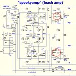
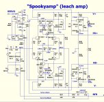
I use a combination of "prior art" .. for example - the spook ..
The professors layout , the "leach like" harmon/ kardon , and what I
know of each section of the amp.
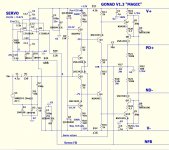
-The VAS has to be "alone" on the board ... this leach can do 200V p-p !!
- the cascode/regulator above the VAS is the "change-over" point ,
everything above this is just low current/low voltage (except for NFB ...for this setup).
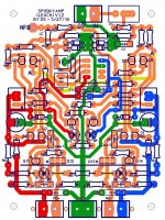
-On my last spooky ... I have the LTP's pretty far away from the cascodes
and also have long traces to each of their current sources. Now I
have the CCS's in the middle and "crossover" at the center ground trace ..
short paths from ccs to ltp AND short paths from LTP to Cascode.
This may seen "anal" .... but not really - I believe the slew rate and thd
can be positively influenced by short paths and a "sectioned" layout.
I applied the same thinking and style on all the IPS's - I'm sure with
premium parts .... we can match the accuphases and other high
priced premium equipment. 🙄
OS
OS,
Which parts are you talking about being of premium quality, all of the devices or only the active components such as the transistors and output devices? Would you need to match components or is your design such as that is not necessary.
Which parts are you talking about being of premium quality, all of the devices or only the active components such as the transistors and output devices? Would you need to match components or is your design such as that is not necessary.
OS,
Which parts are you talking about being of premium quality, all of the devices or only the active components such as the transistors and output devices? Would you need to match components or is your design such as that is not necessary.
Matching ....
These are symmetrical designs - this mean equal.
Not to the point of curve tracing a pnp/npn pair .... but at least go
through a few pairs on the DMM to get "close" (hfe).
The Gonad is the most "picky" (diamond IP) , I know better matched
{models} will give lower THD and better offset.
The spooky NPN (pair) and PNP (pair) should be loosely matched.
The PNP/NPN (difference ) is not as critical.
In the spooky simulation , you can use a totally different P pair compared
to the N pair ... and still do PPM at 150V. Servo works a little harder.
Both amps will ALWAYS give <3-4mV offset. Those trimmers can also
be helpful on either amp ... if you have a slight mismatch.
NO ebay semi's ... new old stock - just the normal from mouser/digikey
fare will be fine.
Caps should be poly/silver mica. Resistors 2%. Electro's 25V-35V for the IPS's
and a straight 100V for the OPS.
OS
Magic resistors + playin' with the "embellishments".
"Magic resistors" (below 1-circled/ R26 and 30)on the hawksford(s)
(memory distortion).
4.7R - 10R lowers H3/5 slightly and also reduces (nearly eliminates)
saturation at the VAS !!
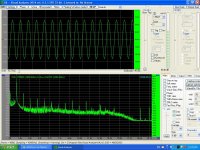
Both the gonad and spook top out at 45-50ppm *170Vp-p.-
-then clip gracefully (below 2/3) at 184 (spook) and 179 (gonad) p-p/4R ... both on 100V rails.
These 2 IPS's should give JK's OPS's quite a "thrashin" - absolute headroom.
80V rails will clip at 146Vp-p !! 😎
PS - yes Kind ... I will concentrate on these 2 amps (BOM as well).
Edit ... WHILE clipping - servo keeps <6mv - both amps ... these are really "primetime" !
FEEL free .. to hook up your 85-90V per rail PS's to these ... they are made for it.
OS
"Magic resistors" (below 1-circled/ R26 and 30)on the hawksford(s)
(memory distortion).
4.7R - 10R lowers H3/5 slightly and also reduces (nearly eliminates)
saturation at the VAS !!
Both the gonad and spook top out at 45-50ppm *170Vp-p.-
-then clip gracefully (below 2/3) at 184 (spook) and 179 (gonad) p-p/4R ... both on 100V rails.
These 2 IPS's should give JK's OPS's quite a "thrashin" - absolute headroom.
80V rails will clip at 146Vp-p !! 😎
PS - yes Kind ... I will concentrate on these 2 amps (BOM as well).
Edit ... WHILE clipping - servo keeps <6mv - both amps ... these are really "primetime" !
FEEL free .. to hook up your 85-90V per rail PS's to these ... they are made for it.
OS
Attachments
Last edited:
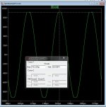
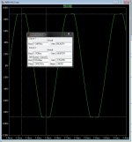
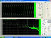
These pictures show the Spooky output on a pc based analyzerPlease, explain the pictures.
Attachments
Last edited:
drill bits, taps and stuff...
Got a cordless drill with variable speed?
That's my preferred way to tap into heatsinks.
1- start with the corresponding hole relating to your tap (see for instance :Thread - Drill & Tap Chart)
2- then get the tap on the drill, set your speed (clutch) to ~minimum (as to not break the tap inside the sink) and start slowly and then reverse after a few turns, repeat front/back until you've tapped the clearance you want... a bit of cutting oil or wd40 helps (a bit, not too much as not to get all "mushy")
If you can, buy taps with "start" thread and "finish" thread, normally numbered 1 to 3 (I mostly use 1 to start and 3 to finish it) that will help...
average time per hole : ~2.5min sometimes faster
like this: http://www.diyaudio.com/forums/solid-state/221741-dx-blame-st-together-dx-super-135.html#post3802159
hope it helps, it's really too easy, you just have to get the feeling for the drill... no manual tapping whatsoever!!!😀😀😀
(...)My progress of building 5 pairs EF3 so slow. I have difficulties to put transistors on heat sink. I hate mechanical things 😡. Anybody please give me a link that describe (tutorial) how to drill heat sink or such like this.(...)
Got a cordless drill with variable speed?
That's my preferred way to tap into heatsinks.
1- start with the corresponding hole relating to your tap (see for instance :Thread - Drill & Tap Chart)
2- then get the tap on the drill, set your speed (clutch) to ~minimum (as to not break the tap inside the sink) and start slowly and then reverse after a few turns, repeat front/back until you've tapped the clearance you want... a bit of cutting oil or wd40 helps (a bit, not too much as not to get all "mushy")
If you can, buy taps with "start" thread and "finish" thread, normally numbered 1 to 3 (I mostly use 1 to start and 3 to finish it) that will help...
average time per hole : ~2.5min sometimes faster
like this: http://www.diyaudio.com/forums/solid-state/221741-dx-blame-st-together-dx-super-135.html#post3802159
hope it helps, it's really too easy, you just have to get the feeling for the drill... no manual tapping whatsoever!!!😀😀😀
OS, I will use your layout as my design reference. You are very fast to make circuit design and layout. Nobody can not catch you 😀.
My progress of building 5 pairs EF3 so slow. I have difficulties to put transistors on heat sink. I hate mechanical things 😡. Anybody please give me a link that describe (tutorial) how to drill heat sink or such like this.
Now I must make so many seven segments display...
Bimo, I plan on very soon putting up a PDF drill template to make preparing a heat sink easier. That will allow folks to print it at 100%, tape it down, centre punch the hole locations and drill accurately. As for tapping, the correct drill size for the tap is important as is the correct lubricant. I would avoid tapping with power tools, it is to hard to feel what is going on And ultimately breaking the tap.
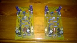
Beginning to stuff the first board...
Beautiful board!
Congratulations.
Thimios.
Maybe we could agree to disagree 😉(...). As for tapping, the correct drill size for the tap is important as is the correct lubricant. I would avoid tapping with power tools, it is to hard to feel what is going on And ultimately breaking the tap.
with a drill clutch, you just CAN'T break a tap...
I have snapped many a tap using a drill. Part of it is being able to hold the drill perfectly straight. A drill press would work better but most don't have any kind of clutch nor reverse. I have found that though they are similar in size, a 3mm tap is much sturdier than a 4-40. I have switched over to 3mm for all my transistor mounting.
Carcass,
Never say never. With the small screw size and small tap size it could happen. Lubrication is important any time you tap into aluminum as it likes to create a burr since it is so soft. Also any tilt of a cordless drill could start the tap crooked and cause it to break. A hand tap is just simple and easy to do with only 10 holes for a 5 pairs build. It also has much to do with the heat sink thickness as everyone is using something different. I would suggest that a two flute tap would be stronger in these small sizes rather than a four flute tap. I don't expect that most of us with experience would have much trouble with either power or manual tapping but for someone who does not do this much or has never done this it could lead to a broken tap which would be no fun if it broke off flush with the surface!
Yes I am a trained machinist, as Terry just said it is oh so easy to break such a small tap. I won't worry about using a drill press for so few holes though I can do that. Somewhere I have a Tapmatic attachment but it isn't worth the hassle for so few holes though I would use it for drilling the holes straight up and down.
Last edited:
OS, how far we are from final ver. NAD 1.3?

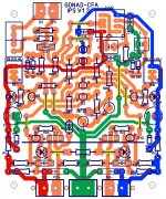
It is ready for the "embarrassment phase" .... show me my errors.
(below 1/2).
Updated the board , the schema , and a BOM.
-"X" will also allow to run the servo inverting (like the 1.2) .... cut the
thin trace above C10 , R27 to "X" , jumper the other X's. Default is
non-inverting fed to current FB.
-labeled "ccs pos/neg adj." , (R5/10)these could be jumpered and omitted ...
(R6/9) - can be a cheap 680R ... if you can't afford 2-2us$ trimmers. 😱
Servo actually makes the trimmers redundant , but you might want to
"tweak" the VAS current with them (or balance a "sloppy" input pair).
-input cap is 3.5mm wima / 5/7.5/or 10mm LS.
-Seen thimios's v1.2 - every spacing and layout consideration has
been "anally" addressed. 😀
Gonad 😎😎 is by far the best "simplicity to performance" amp I've
run across. Only the "spook" can beat it (not by much).
OS
Attachments
Last edited:
OS,
I like the name Master Slewmaster by OS, better than Gonad, easier on the marketing side!
Are you going to update post #1 to the V1.3 and will this just point to this or another later post #? How does the first post work when you are all done, will it contain the latest files or do you just go to the pointed file #?
What's wrong with "Gonad" , it got a pair ! 😀
A real man's amp ....
I'm even going to re-build larger speakers (12" 3-way Yamaha) to see
just how big of a pair it's got.
OS
A real man's amp ....
I'm even going to re-build larger speakers (12" 3-way Yamaha) to see
just how big of a pair it's got.
OS
- Home
- Amplifiers
- Solid State
- Slewmaster - CFA vs. VFA "Rumble"