OS,
Who would run that high a voltage on the input stage let alone the outputs?
Crazy people.
PS - like ESP .... Project 117
My triple and these IPS's would be much more "graceful" for the job.
why 1Kw ?? ... for me 60mm Xmax ! 😀 (below)
OS
Attachments
My speaker is designed to do 1.25" peak travel and that is on an equivalent to about a 7' cone. But it won't take anywhere near that much power.
OS how many Semetechs would it take to do 220 p2p (1Hp) and what THD would it be @? If you have a moment...Thanks
Spooky + 5 pair of the big semetech's would be 220 v p-p
@ <50ppm ...
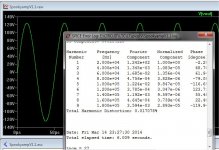
I've even simulated at 135V rails and reached 250vp-p (below).
This is where even the spook gets "sloppy" .01% 😀
Both OPS and IPS would have to be modified to handle 135V.
track distance , track width and 2 more OP pairs (7 pair semelab).
ONE insane subwoofer driver with a KVA trafo + 100k uf !
PS - I would even stretch a 7-8 pair board out to 350mm long to distribute the heat
from a 1KW amp out. Thats 3200W of output device (semelab mg6332/9412)
OS
Attachments
Last edited:
OS take a break we can't follow you, all my parts are gone out ,no boards ,no small signal transistors ,no anymore capacitors no anymore resistors my junk box is empty.😱
Last edited:
OS ,
Several people did ask me to go for the 5P version,so you can decide which version to build.
Maybe organize somekind of poll between 5P and 3P
What do you think?If we reach 10 pieces for each version I could maybe do both.
Several people did ask me to go for the 5P version,so you can decide which version to build.
Maybe organize somekind of poll between 5P and 3P
What do you think?If we reach 10 pieces for each version I could maybe do both.
Buy more !OS take a break we can't follow you, all my parts are gone out ,no boards ,no small signal transistors ,no anymore capacitors no anymore resistors my junk box is empty.😱
Consume , my friend ..
This is our purpose in life ... to spend $$ ... stimulate the economy.
More , more .... MORE ! 😀
OS
OS ,
Several people did ask me to go for the 5P version,so you can decide which version to build.
Maybe organize somekind of poll between 5P and 3P
What do you think?If we reach 10 pieces for each version I could maybe do both.
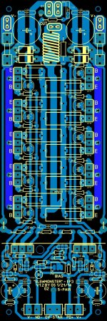
I "augmented" the 5-pair (5.25mm double sided rails).
Through holes at each OP device.
Should be able to handle 20+ A per rail.
PS - the 5 pair is only 35mm longer (9"/225mm total) than the 3P .. ? Why not ?
It will still fit the 10.125" (260mm) heatsink USA deal...
OS
Attachments
I "augmented" the 5-pair (5.25mm double sided rails).
Through holes at each OP device.
Should be able to handle 20+ A per rail.
PS - the 5 pair is only 35mm longer (9"/225mm total) than the 3P .. ? Why not ?
It will still fit the 10.125" (260mm) heatsink USA deal...
OS
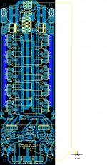
I agree that if some of us are going to have boards made, especially with PTH at key locations, then there is no reason to not use the top for added current carrying capability. After all, it won't cost any more since the PTH puts copper on the top anyway.
I'm doing a very clean (hyper-anally retentive) re-draw of your 5P art to address a few minor issues that cropped up when I did a gerber export and loaded the gerber into a viewer. The 'issues' my not be a problem but I'd like the software to give me no warnings when being viewed. I hope you don't mind. My intent is to faithfully reproduce your layout that will export cleanly.
Hi Guys,
I'm trying to learn something here. I have a question about the ground scheme on the board. I see there are two separate ground connections on the board. What is the reason that that the ground doesn't just run all the way through on the PCB?
Thanks, Terry
I'm trying to learn something here. I have a question about the ground scheme on the board. I see there are two separate ground connections on the board. What is the reason that that the ground doesn't just run all the way through on the PCB?
Thanks, Terry
Hi Guys,
I'm trying to learn something here. I have a question about the ground scheme on the board. I see there are two separate ground connections on the board. What is the reason that that the ground doesn't just run all the way through on the PCB?
Thanks, Terry
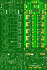
Hi Terry ,INP and cap.multip.ground connected to star ground via separate wire.
In this way <<dirty ground>> from OUT isn't affect the sensitive INP.
Attachments
Last edited:
I think the 5P boards are best. They aren't much longer than the 2P or 3P anyway. I will probably use 2P or 3P outputs and space them out on the 5P boards for better thermal management.
SlewMonster 5P OPS 'Re-Visioned'
Getting closer. Just need to error check against the schematic and put on the component designators.
Minor push / pull here and there but I think it is firmly in line with OS's intentions. This artwork intended for production via a board house and makes use of the top copper for added current handling since top copper will be present for the PTH option anyway. It could be produced with only the bottom copper.
Left is OS's original v1.2 art and the right is mine.
I think most builders will likely go for the 5-pair OPS. If there is one thing DIYers do well is over doing it 😀.
Attachments
On this or a similar thread there was some one the said there was a need for a large Cap next to each output device, does that have any bearing here, or can that issue be resolved in the power supply right next to the board...and incorporate the protection dc detection etc.
Super Superior Stuff from OS and all others, this is going a long way on this forum. THANKS
Super Superior Stuff from OS and all others, this is going a long way on this forum. THANKS
Krisfr,
If I am seeing the boards correctly that both OS and Jason have just posted both boards have distributed capacitance right at the output devices. It seems they are both thinking very similar with the added trace width for the output section. I like Jason's idea of using the copper on both sides of the board but I wonder if that will cause some inductive problems or not.
If I am seeing the boards correctly that both OS and Jason have just posted both boards have distributed capacitance right at the output devices. It seems they are both thinking very similar with the added trace width for the output section. I like Jason's idea of using the copper on both sides of the board but I wonder if that will cause some inductive problems or not.
Krisfr,
If I am seeing the boards correctly that both OS and Jason have just posted both boards have distributed capacitance right at the output devices. It seems they are both thinking very similar with the added trace width for the output section. I like Jason's idea of using the copper on both sides of the board but I wonder if that will cause some inductive problems or not.
All I am doing is redrawing OS's layout to make it really pretty (at least to my eyes anyway). OS has already shown using both sides just prior to my redraw.
I doubt there would be any issues with using both sides, they are handling the same signal.
A string of parallel caps is like a string of resonators. It will have transmission-line-like behaviors and multiple resonance modes. However the 22uF caps used here are very lossy. 10uF and under lytic caps are used to keep even the most spastic high-speed opamps stable.
I would be more worried about the inductance of the return path through the caps. The loop inductance from collector to emitter is the important thing here.
I would be more worried about the inductance of the return path through the caps. The loop inductance from collector to emitter is the important thing here.
Why not do some basic ground plane stuff if a second layer is available? Ground+power planes will do wonders for decoupling and shielding. You can put the ground plane on the top side so the power planes are between the ground plane and the heatsink. This way the high-current magnetic fields will be confined between the ground plane and heatsink, and shorted out before they go into the chassis.
Jason,
I am not sure but it looks like you have two sets of holes for the capacitors so you can use two different diameter capacitors of your choice?
I am not sure but it looks like you have two sets of holes for the capacitors so you can use two different diameter capacitors of your choice?
- Home
- Amplifiers
- Solid State
- Slewmaster - CFA vs. VFA "Rumble"