May be this thread can help to explain.
http://www.diyaudio.com/forums/software-tools/185906-op-amp-virtual-ground-spice.html#post2518360
jer 🙂
http://www.diyaudio.com/forums/software-tools/185906-op-amp-virtual-ground-spice.html#post2518360
jer 🙂
Here is sort of a little better explanation of how the circuit works.
http://www.diyaudio.com/forums/analog-line-level/211340-active-crossover-help.html#post2996899
If you are using a solid constant unreserved power supply than then the Zener diode Vref method won't be an issue at all.
But, As you stated you are planning on running from batteries so two things of importance has to be considered.
Power saving from a constant unneeded extra current draw, and, the Vref needs to stay exactly 1/2 Vcc in order to maintain integrity of the signal as the voltages starts to droop.
jer 🙂
Last edited:
In the circuit you have posted for one channel, it uses 9 opamp stages this leaves one opamp stage left over assuming you are using a dual opamps.
Else for stereo you can use just a single TL071 for your virtual ground driver if you wish.
jer 🙂
i will keep everything mono.
it is more simple and uses less components.
i don´t need effects like "guitar is left and singer right" or "helicopter is flying through the room".
i want a monoblock as this is my prefered way of listening to reggae/dub and almost never listen to anything else.
wow, the thread has a new dynamic!
the doc i was refferring is this one:
http://www.eng.yale.edu/ee-labs/morse/compo/sloa058.pdf
page 16 shows the sallen key lpf with single supply, where the cap is connected to ground.
i don´t know what to believe.
i will try the voltage divider via an opamp on the breadboard.
the doc i was refferring is this one:
http://www.eng.yale.edu/ee-labs/morse/compo/sloa058.pdf
page 16 shows the sallen key lpf with single supply, where the cap is connected to ground.
i don´t know what to believe.
i will try the voltage divider via an opamp on the breadboard.
Yes pages 3 and 4 is what I am trying to explain.
Notice that on page 16 that R3 & R4 are of equal value and produce the 1/2 V ref that is needed by the opamp stage +input.
The second schematic shows a 1/2Vref point that is required.
I prefer to keep all of the signal paths uniform as they would be if using a bipolar supply.
The cost in THD using other imbalanced configurations I am not sure of.
But the real error in your simulation was in fact from the improper termination of the two input resistors and I have modified the model to show this.
jer 🙂
Attachments
Last edited:
how good is that?
a guy sitting in michigan explaining me how to design a battery driven preamp that will be used to amuse reggae fans in germany.
sometimes i love the internet and the fact that i live in the pacified part of the planet.
life could be so good ..... if there weren´t those damned exams coming up.
a guy sitting in michigan explaining me how to design a battery driven preamp that will be used to amuse reggae fans in germany.
sometimes i love the internet and the fact that i live in the pacified part of the planet.
life could be so good ..... if there weren´t those damned exams coming up.
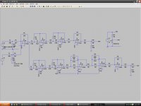
In this screen shot I show the resistors properly terminated but the capacitors are as you had them and it still shows an error!!
They may very well work under this condition as they are blocking DC but I suspect there will be issues as I don't follow this type of practice in the real world.
But this is definitely some thing that Spice doesn't like and typically will reflect as such in the real world, But not always. 😉
jer 🙂
They may very well work under this condition as they are blocking DC but I suspect there will be issues as I don't follow this type of practice in the real world.
But this is definitely some thing that Spice doesn't like and typically will reflect as such in the real world, But not always. 😉
jer 🙂
Attachments
Ahhh,ha,ha,ha....Well I have been designing and building battery powered opamp circuits since the early 80's.
I do hope that you are learning from my mistakes!!
jer 🙂
I do hope that you are learning from my mistakes!!
jer 🙂
....you do not have 100k resistor at the outputs to vref.
but i guess that would not change anything.
but i guess that would not change anything.
considering the very low use of power of the whole circuit...
i think about driving it with two 9v-blocks.
the tpa3116-boards take a large range of dc-input up to 25v very well.
so when i want to use the setup indoors, i can use a psu of choice and still use the preamp.
that would be good for example when the sla batteries are empty.
this circuit should run an eternity with two 9v-blocks, right?
i can simply connect them the same kind of dc-plug i use atm.
Nope it doesn't, this is because the capacitor is blocking any DC (hence DC blocking cap).
And the AC signal that it coming out of the capacitor is now referenced across the resistor to your V- as ground for the next device that is connected to it as I explained in post #110.
jer 🙂
And the AC signal that it coming out of the capacitor is now referenced across the resistor to your V- as ground for the next device that is connected to it as I explained in post #110.
jer 🙂
Yes, it would run for quite a while using a couple of battery's but you could easily add a wallwart to power the preamp if needed.
jer 🙂
jer 🙂
If you are running off of two 9V blocks then you can forget the Vref thing all together and tie that part as it is ground as normal.
But then you will have the offset issue of one battery drooping lower than the other.
jer 🙂
But then you will have the offset issue of one battery drooping lower than the other.
jer 🙂
Last edited:
how good is that?
a guy sitting in michigan explaining me how to design a battery driven preamp that will be used to amuse reggae fans in germany.
sometimes i love the internet and the fact that i live in the pacified part of the planet.
life could be so good ..... if there weren´t those damned exams coming up.
What is even more cooler is when one gets to converse in these very threads with the actual designer of these very cool little devices!!!!! 😉
jer 🙂
Last edited:


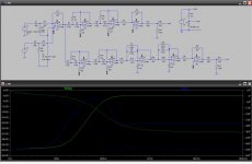
how about that?
why is vlp rising above 3khz?
is the phase shift ok?
edit:
maybe vlp looks crazy because of the way v3 is made.
it is not really simulating an audio signal.
when i copy v1 and insert that in v3's place ltspice is not able to simulate.
i'll play around a bit with the settings....
Last edited:
Hmmmmm.........Not sure when I duplicated it still works but it does something different then results you have shown.
I am not proficient enough with LTspice to know all of its quirp's.
I am more familiar with Circuitmaker2000 as I have been using it since it came out in the 90's.
jer 🙂
I am not proficient enough with LTspice to know all of its quirp's.
I am more familiar with Circuitmaker2000 as I have been using it since it came out in the 90's.
jer 🙂
Can I just make a quick observation on your power supply arrangements......
There seems to be some confusion over "single rail operation" (which is how the design started) and creating a "virtual ground", which is how its (nearly) ended up.
With single rail you refer everything to what is effectively the battery negative. Vref becomes a true DC bias voltage (the zener arrangement earlier) and provides constant DC operating conditions as the battery voltage falls. It is not a signal reference point. The only real downside is that the clipping at max output will become asymmetric as supply voltage falls... which probably isn't an issue as you will be running way below that threshold. A good approach there would be to set the reference voltage to a "compromise" value that gives clipping on one side with new batteries, then as voltage falls clipping becomes equal, and then as voltage falls further, the clipping moves the other way.
If you move to "virtual ground" then all points now refer to this new point of reference. Clipping would be symmetrical at all times. Also R27 and R28 are not needed as drawn, in fact they should be on the other side of the cap and referred to the virtual ground. Although OK in simulation, your input signal grounds on V2 and V3 need moving to the virtual ground for a real build.
As drawn and if you used it as drawn (using your marked battery negative ground as ground) then the output would acquire a DC voltage of half supply due to R15.
Its a subtle difference between the two schemes, both are valid, but you need to fully understand what those differences are and how to correctly wire each one.
(i think) i understand the virtual ground thing better.
having one reference for audio signal is the way for me to look at it.
earlier in the thread i said that the caps to ground in the lp-section is ginving me a bad headache.
so does connecting r15 and r16 to ground.
i'm still a noob and although i would like to understand everything this is still beyond my scope.
so with that part of the design i'm not sure.
of course it would be nice to really know what i do, but on the other hand i want a good working preamp.
with ps i see more advantages for the voltage divider method.
+ efficiency
+ symmetry
- one more opamp
The caps in the LPF section either go to the virtual ground (or vref as you still call it) in the diagram above, or, in the true single rail version they go to the 0 volt line (battery negative).
mooly, what are the advantages of a "true single rail" design?
do i see it right that the design of the ps (zener or opamp) has nothing to do with the actual choice of filter design (single rail or virtual mass)?
do i see it right that the design of the ps (zener or opamp) has nothing to do with the actual choice of filter design (single rail or virtual mass)?
- Status
- Not open for further replies.
- Home
- Source & Line
- Analog Line Level
- Designing a noob-preamp (single supply)