Though i don't get the idea here (truncated post 🙂) but the link is a good read though so thanks.
P.S I read the damn things multiple times and the application notes (AN-1192, AN-1849) and to make sure the LM4780 also, so your point being???🙂
Best regards.
IDK you seem to ask less questions about the technical data sheet than schematics you got from the net. It's my impression you heavily favor subjective snippets here and there over thread contributors objective / practical experience. you seem to be from the less is more camp ( less parts = sonically superior)
Last edited:
IDK you seem to ask less questions about the technical data sheet than schematics you got from the net. It's my impression you heavily favor subjective snippets here and there over thread contributors objective / practical experience.
Okay let's get this off your chest (mine too)...
Dear infinia, i ask the questions i don't know the answer to like any normal person, what i find in the answers (if any) i take what i like and leave what i don't (simple right?), this thing the whole idea of audio DIY is having fun and maybe learn something or two "along the way" (Nat King Cole)🙂...
Back to your impression on what i favor and what i don't, the datasheet implementations are almost a textbook inverting and non inverting configurations, what's there to ask about? what really intrigues me if there is a way to make such a cheap and simple circuit to sing beautifully and up to a certain standard as i already own a good collection of vintage and modern audio gear so why bother?
Now if that's not the meaning of DIY then i don't know what it is.
Best regards.
yupi already own a good collection of vintage and modern audio gear so why bother?
good luck
Now, the more interesting question in my mind is whether the inverting configuration is worth the extra trouble to deal with its low input impedance. Even 10 kΩ is kinda low, but probably OK - unless you use a volume pot, then you will need a buffer. I don't like the resulting 200 kΩ feedback impedance, though. Even the 10 kΩ I'm using will show up in the output noise. So given that I've painted myself into the low impedance corner for noise reasons, I am forced to use an op-amp driver. This adds cost and complexity (and plenty of opportunities to screw up and actually get much, much worse measured THD performance).
You can try a low impedance T-network feedback with input buffer of course, see http://www.diyaudio.com/forums/chip...-better-feedback-solution-46.html#post1274340
You can try a low impedance T-network feedback with input buffer of course, see http://www.diyaudio.com/forums/chip...-better-feedback-solution-46.html#post1274340
Negative effect on the amplifier bandwidth, there are compensation of course but i didn't like the idea very much.🙂
Best regards.
The new schematic, it is based on Bob Cordell's super clone, any input is welcome...
Best regards.
An externally hosted image should be here but it was not working when we last tested it.
Best regards.
Negative effect on the amplifier bandwidth, there are compensation of course but i didn't like the idea very much.🙂
Do you have any data to support that claim? Why dont' you like the idea?
The new schematic, it is based on Bob Cordell's super clone, any input is welcome...
It may be over the top, but you can use two-terminal CCS for R2/R3, be it simple J-fet wired as CCS, or 2 complementary Tr, 2 LEDs and 2 resistors, also wired as two-terminal CCS for each supply branch. It will give LME excelent isolation from the rest of the system, but it's good as it is anyway.
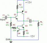
Why not use a simple buffer? You could use C 13,14,15,16 D1 and D2 ( 12 V) , R 2,3 .They would provide the supply rail. Dump all input capacitors and resistors except what is shown on the circuit. I have used this before and it sounds very good. By that I mean it seems to be fairly transparent. Doesn't add much that you hear as some form of degradation. It will measure worse than the LME49710 or the LM3886! But it does sound OK !
Note that you can even drop the input capacitor if the previous stage has a coupling cap and also if the output dc of the previous stage is very low. Bias current of Q1 and Q2 is controlled by R2 and the CCS ( Q3, Q4 ). Any input dc will superimpose itself on the -0.65 V seen at the output. Anything within +/- 1 V at the input should also be OK. So it's quite flexible. Avoiding the input cap is a good thing sometimes ( especially when you can't get a really good one at a sane price !). I have come across situations where the input cap did help the sound though it was not really required. Not quite sure why it was so ! Try it out ! Skip all the extra caps in the supply except one electrolytic on each rail. Then add the others after you hear the amp. See if they make any difference.
If I was very critical I'd use a transistor / zener combination on the rails. That always works very well .
Forgot to add. Q1,3,4 can be BC547B or C and Q2 BC 557 B or C.
Attachments
Last edited:
The buffer shown is loaded with 1K ohm. Distortion at 2 V rms seems to be below 0.01 %. So the LM3886 can use 1K and 22K as feed back resistors.
Will be interesting to see how this simple discrete circuit compares with the LME opamp in this application. Time for me to get some LME49710 !🙂
Will be interesting to see how this simple discrete circuit compares with the LME opamp in this application. Time for me to get some LME49710 !🙂
Last edited:
The new schematic, it is based on Bob Cordell's super clone, any input is welcome...
🙂 Comments (just my thoughts)
You have no compensation cap and no series output inductor or resistor shown. It may well be fine under normal conditions but I would want to be sure it was 100% stable into any reasonable load.
Its inverting of overall phase. Does that matter ? Its probably undetectable in listening, and if you want to eliminate another opamp stage then you can leave it as it is. You could also just wire the speaker sockets in reverse, red to ground and black to output.
I would want to know how the circuit behaved on power on and power off with regard to thumps and bangs although personally, unless it were 100% silent in that regard, then I would want to fit a solid state speaker relay.
🙂 ...... a solid state speaker relay.....
Has anyone done a listening test comparing a normal relay protection with solid state relay protection? Each has pro's and cons technically but do they audibly affect the sound in different ways ?
Has anyone done a listening test comparing a normal relay protection with solid state relay protection? Each has pro's and cons technically but do they audibly affect the sound in different ways ?
I've been using mine for a couple of years now and am very pleased. Listening test... yes... it was because my conventional relays produced very audible distortion (on low power sine wave) that led me to investigate SS. I would never go back to mechanical switches for either speaker or small signal.
No.in the answers (if any) i take what i like and leave what i don't (simple right?),
You should be learning to sort the wheat from the chaff.
That means that sometimes you have to take the medicine that does not taste nice.
It is NOT a case of "I like that answer" so I will take it as Gospel.
When I first read Cordell's book and saw that schematic, I was immediately skeptical.
I have reviewed it a few times since and still think that some of the proposals are flawed:
A high quality opamp as a "Buffer".
Inverting mode.
Adoption of the National Zobel resistor value, 20r//3r16.
Added capacitance on the -IN Pin.
Similar values for R6 & R7.
Similar values for R8 and R9.
Gain = +26dB.
Unmatched resistance on the 3886 input pins (using the servo to remove this error).
No resistor in the opamp feedback loop.
Removal of the servo without correcting the input pin resistor error.
The differences noted below make the posted sch even worse.
No Thiele Network on the Output.
No explanation of how or where to reference the Signal Ground to the Power Ground.
Moving the decoupling to common grounding points away from both the chips
Last edited:
Do you have any data to support that claim? Why dont' you like the idea?
Below is a link to a paper analyzing the effect of the T feedback network on the amplifier's bandwidth and how to compensate for it.
Frequency Performance Compensation of Operational Amplifiers with the ?T? Feedback Network - Springer
Best regards.
Why not use a simple buffer? You could use C 13,14,15,16 D1 and D2 ( 12 V) , R 2,3 .They would provide the supply rail. Dump all input capacitors and resistors except what is shown on the circuit. I have used this before and it sounds very good. By that I mean it seems to be fairly transparent. Doesn't add much that you hear as some form of degradation. It will measure worse than the LME49710 or the LM3886! But it does sound OK !
Note that you can even drop the input capacitor if the previous stage has a coupling cap and also if the output dc of the previous stage is very low. Bias current of Q1 and Q2 is controlled by R2 and the CCS ( Q3, Q4 ). Any input dc will superimpose itself on the -0.65 V seen at the output. Anything within +/- 1 V at the input should also be OK. So it's quite flexible. Avoiding the input cap is a good thing sometimes ( especially when you can't get a really good one at a sane price !). I have come across situations where the input cap did help the sound though it was not really required. Not quite sure why it was so ! Try it out ! Skip all the extra caps in the supply except one electrolytic on each rail. Then add the others after you hear the amp. See if they make any difference.
If I was very critical I'd use a transistor / zener combination on the rails. That always works very well .
Forgot to add. Q1,3,4 can be BC547B or C and Q2 BC 557 B or C.
The buffer shown is loaded with 1K ohm. Distortion at 2 V rms seems to be below 0.01 %. So the LM3886 can use 1K and 22K as feed back resistors.
Will be interesting to see how this simple discrete circuit compares with the LME opamp in this application. Time for me to get some LME49710 !🙂
Hi Ashok, nice and simple design i am going to build both the buffers and listen to each of them. One question though...C2=22uF polar or bipolar?
Best regards.
🙂 Comments (just my thoughts)
You have no compensation cap and no series output inductor or resistor shown. It may well be fine under normal conditions but I would want to be sure it was 100% stable into any reasonable load.
Your thoughts are always welcome 🙂, if you mean the compensation cap parallel to the feedback resistor (the series RC branch) i can add that. As for the output R//L network i'll leave it out for now and add it later if the speaker cable combination need it.
Its inverting of overall phase. Does that matter ? Its probably undetectable in listening, and if you want to eliminate another opamp stage then you can leave it as it is. You could also just wire the speaker sockets in reverse, red to ground and black to output.
That's the plan. 🙂
I would want to know how the circuit behaved on power on and power off with regard to thumps and bangs although personally, unless it were 100% silent in that regard, then I would want to fit a solid state speaker relay.
If you mean the power on thumb, the power supply have a soft start circuit with a rather large start up time so i guess that will help?
Best regards.
No.
You should be learning to sort the wheat from the chaff.
That means that sometimes you have to take the medicine that does not taste nice.
It is NOT a case of "I like that answer" so I will take it as Gospel.
When I first read Cordell's book and saw that schematic, I was immediately skeptical.
I have reviewed it a few times since and still think that some of the proposals are flawed:
A high quality opamp as a "Buffer".
Inverting mode.
Adoption of the National Zobel resistor value, 20r//3r16.
Added capacitance on the -IN Pin.
Similar values for R6 & R7.
Similar values for R8 and R9.
Gain = +26dB.
Unmatched resistance on the 3886 input pins (using the servo to remove this error).
No resistor in the opamp feedback loop.
Removal of the servo without correcting the input pin resistor error.
The differences noted below make the posted sch even worse.
No Thiele Network on the Output.
No explanation of how or where to reference the Signal Ground to the Power Ground.
Moving the decoupling to common grounding points away from both the chips
For the last time i ask you politely, your help is not welcome so don't.
Below is a link to a paper analyzing the effect of the T feedback network on the amplifier's bandwidth and how to compensate for it.
You're telling me that I'm supposed to pay $40 to see the article? Anyway, I think I've already read that article, and IIRC all that in needed is to place a small compensation capacitor in parallel to shunt resistor in T-feedback network, and IIRC it's there only to extend a freq. response a tiny bit comparable to non-inverted wired opamp.
- Status
- Not open for further replies.
- Home
- Amplifiers
- Chip Amps
- Inverting LM3886