Fair enough... can I ask then, what is the function of R3 ? And the same question for C8 really.
As for R3 that's a quote from Mark Hennessy's site...
Besides that, the datasheet example for the inverting configuration includes it and also it's mentioned in infinia's post #47.the 33K is just to ensure that C1 doesn't develop a charge across it - this is just good practice
Again a quote from Mark Hennessy's site 🙂...
He refers to this capacitor as the "ultrasonic filter" which i am sure you have seen it included in many circuits for the inverting and non-inverting configurations.There is also an ultrasonic filter which is normally omitted. Personally, I believe in such measures - as well as swamping the cable capacitance, it stops noise from phones and the like getting onto the audio signal.
I am really appreciate you being helpful so thanks Mooly. 🙂
Best regards.
OK 🙂
In your circuit in post #59, the DC voltage at R3 is essentially zero volts anyway. What R3 does is upset the DC balance of the 220ks you want to use. The only reasonable place for R3 is to connect it to the other side of the input cap where it would tie the input side of the cap to ground.
In practice, the only way the input cap can develop a "charge" is if the amp input is left unconnected (floating) and the input then connected to a source that has DC voltage present (so the cap acquires the differential voltage between the source input and the inverting input) and then that source voltage is removed by unplugging it from the input.
All you need in practice is a 1meg connected to the left side of the input cap and the other end to audio ground.
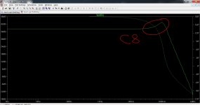
C8 will cause a peak in the loop gain of the amp. I just put your values into a basic opamp circuit (not an LM3886) to show you what it does.
In your circuit in post #59, the DC voltage at R3 is essentially zero volts anyway. What R3 does is upset the DC balance of the 220ks you want to use. The only reasonable place for R3 is to connect it to the other side of the input cap where it would tie the input side of the cap to ground.
In practice, the only way the input cap can develop a "charge" is if the amp input is left unconnected (floating) and the input then connected to a source that has DC voltage present (so the cap acquires the differential voltage between the source input and the inverting input) and then that source voltage is removed by unplugging it from the input.
All you need in practice is a 1meg connected to the left side of the input cap and the other end to audio ground.
C8 will cause a peak in the loop gain of the amp. I just put your values into a basic opamp circuit (not an LM3886) to show you what it does.
Attachments

OK 🙂
In your circuit in post #59, the DC voltage at R3 is essentially zero volts anyway. What R3 does is upset the DC balance of the 220ks you want to use. The only reasonable place for R3 is to connect it to the other side of the input cap where it would tie the input side of the cap to ground.
In practice, the only way the input cap can develop a "charge" is if the amp input is left unconnected (floating) and the input then connected to a source that has DC voltage present (so the cap acquires the differential voltage between the source input and the inverting input) and then that source voltage is removed by unplugging it from the input.
All you need in practice is a 1meg connected to the left side of the input cap and the other end to audio ground.
Point taken, will move the resistor to the left side of the input capacitor.
C8 will cause a peak in the loop gain of the amp. I just put your values into a basic opamp circuit (not an LM3886) to show you what it does.
So what value do you suggest for this capacitor to filter out RF noise? and why do many chip amp (LM1875, LM3875, LM3886) implementations include this cap between the amplifier inputs as a means of filtering out RF frequencies?
Best regards.
Last edited:
I would probably filter RF noise at the inputs to the complete amplifier tbh. Is the LM3886 (and others) particularly prone to this problem anyway ?
Using a cap is a little bit similar to this technique,
http://www.diyaudio.com/forums/analog-line-level/196461-different-opamp-compensation-technique.html
but the cap only comes into play at higher frequencies wheras the resistor doesn't.
The cap just seems a brute force way of imposing a filter to me, when there may not even be a problem to begin with. That depends on your environment and what radiated energy and RF signals are flying around and at what strengths.
I would probably filter RF noise at the inputs to the complete amplifier tbh. Is the LM3886 (and others) particularly prone to this problem anyway ?
Using a cap is a little bit similar to this technique,
http://www.diyaudio.com/forums/analog-line-level/196461-different-opamp-compensation-technique.html
but the cap only comes into play at higher frequencies wheras the resistor doesn't.
The cap just seems a brute force way of imposing a filter to me, when there may not even be a problem to begin with. That depends on your environment and what radiated energy and RF signals are flying around and at what strengths.
Then why did National insisted in including this cap in almost every schematic in the LM3886 and LM4780 datasheets? and if i may ask what is the use of such simulation? can we simulate an LM318 circuit for example and then extrapolate the results to the LM3886 in the same circuit?
Also there is quote from the National's datasheet concerning R3 (47k) and its function...
Thanks for your patience.🙂Sets the amplifier's input terminals DC bias point when Cin is present in the circuit. Also works with Cin to create a high pass filter at
Fc = 1/(2πRin*Cin). If the value of Rin is too large, oscillations may be observed on the outputs when the inputs are floating. Recommended values are 10kΩ to 47kΩ.
Best regards.
R3 should be moved to the other end of C1. Then change the value to 470k or 1M0
C8 should be disconnected from -IN
Instead split R1 into two 5k1 in series. Attach C8 to the junction between the new R1.
C5 should be connected to C3. This is the HF Power Ground.
C2 should be connected to C4. This is the MF Power Ground.
Now connect these two power Grounds.
Connect C6 to the commoned Power Ground.
Connect the commoned Power Ground to the Main Audio Ground (MAG).
Remove the Signal Ground and connect R2, R3, C7 C8 to the Input Signal Return.
Connect the Input Signal Return to the MAG.
Last edited:
No problem 🙂 I haven't got all the answers though 😀
If I were building a chip amp then I would want to test and see for myself what the score was but I would use data sheets and recommended circuits as a baseline. I haven't studied the ins and outs of the LM3886 but it will follow basic theory and practice although obviously be different in certain specific areas determined by the spec of the device.
If National deem the cap necessary then I think you have to go along with that unless you have the means to test for yourself how including it may cause a trade off against some other aspect of the performance.
In that quick sim I did, I used your values... don't National use feedback network values (the resistors) some ten times lower than your design. If so then you are looking at a much smaller cap than 300pf, probably something nearer 33 or 47pf.
R3 should be moved to the other end of C1. Then change the value to 470k or 1M0
C8 should be disconnected from -IN
Instead split R1 into two 5k1 in series. Attach C8 to the junction between the new R1.
C5 should be connected to C3. This is the HF Power Ground.
C2 should be connected to C4. This is the MF Power Ground.
Now connect these two power Grounds.
Connect C6 to the commoned Power Ground.
Connect the commoned Power Ground to the Main Audio Ground (MAG).
Remove the Signal Ground and connect R2, R3, C7 C8 to the Input Signal Return.
Connect the Input Signal Return to the MAG.
The imperative, urgent and pressing nature of these points doesn't really mean a thing to me other than "somebody on the internet said that..." i.e gossip or old wives tales so unless you take the effort to explain yourself in some logical human form then simply don't. Thanks anyway.
No problem 🙂 I haven't got all the answers though 😀
If I were building a chip amp then I would want to test and see for myself what the score was but I would use data sheets and recommended circuits as a baseline. I haven't studied the ins and outs of the LM3886 but it will follow basic theory and practice although obviously be different in certain specific areas determined by the spec of the device.
I agree with all of the above. 🙂
If National deem the cap necessary then I think you have to go along with that unless you have the means to test for yourself how including it may cause a trade off against some other aspect of the performance.
In that quick sim I did, I used your values... don't National use feedback network values (the resistors) some ten times lower than your design. If so then you are looking at a much smaller cap than 300pf, probably something nearer 33 or 47pf.
There's no mention in the datasheet or anywhere else audio about this capacitor value in link with the feedback network values of the amplifier or even with the configuration of the amplifier.
Best regards.
If you care you would take the time to read my previous posts on each of these points. They will all be explained, usually in detail, over the years.The imperative, urgent and pressing nature of these points doesn't really mean a thing to me other than "somebody on the internet said that..." i.e gossip or old wives tales so unless you take the effort to explain yourself in some logical human form then simply don't. Thanks anyway.
But I keep having to repeat myself because many Members refuse to research their project.
Last edited:
where did you found that schematic?Another question...
In the schematic below the feedback loop is taken from after the output resistance (0R22) Why is that? and what is the purpose of this resistance anyway?
An externally hosted image should be here but it was not working when we last tested it.
Best regards.
where did you found that schematic?
Over there...
Tubes & The Gainclones
and there are something similar here....
HiFiLab - Amplifier
P.S your avatar really scares me.🙂
Best regards
Essentially , bias currents of the LM3886 pass through R4 ( and R6 !) and R2. If we assume zero offset voltage at the input ( +/- ) terminals of the opamp , any difference in voltage across R4 and R2 will cause a dc ( offset) output voltage. So ideally R4 and R2 should be equal and as low as practically possible.C7 is essentially to short out any ac drop across R2 and also I guess to short out the noise across R2 and 1 uF should be OK.
If I were you I'd use 1K for R1 and 22K for R4 and R2. I might even short out R2 ( 0 ohms!) and see if the offset is affected much. If the output offset is within +/- 50 mV or so I'd short out R2 ! Then add an opamp at the input that can drive 600 ohms ! Like a NE5534 or a newer opamp? Socket the opamp so that you can try other variants also.
Actually having negative feedback from the 3886 output pin is ideal. The 0.22 ohms will then come in series with the speaker load and will add to the resistance of the connecting cable ( and connector joint ) which most likely is also high at around 0.2 to 0.5 ohms ? Now the output impedance seen by the speaker will be Zout ( of 3886) + 0.22 ohms + speaker wire resistance + connector resistance . It might/will give a small bump in the LF response. This can be good unless the effect is too much. Remember that in most speakers the woofer has an inductor in series with it. Often these can have a resistance of 0.2ohms or more by themselves ! Best method is to check it out. Try it both ways ! Ideally R6 ( 0.22 ohms) should be a non inductive type.Flat metal film ( boxed resistor) would be good. 5 Watts should be OK for normal use. So 0.22 ohms isn't to high a value. If used within the NFB loop and if it's inductive it can lead to problems !
Last edited:
Essentially , bias currents of the LM3886 pass through R4 ( and R6 !) and R2. If we assume zero offset voltage at the input ( +/- ) terminals of the opamp , any difference in voltage across R4 and R2 will cause a dc ( offset) output voltage. So ideally R4 and R2 should be equal and as low as practically possible.C7 is essentially to short out any ac drop across R2 and also I guess to short out the noise across R2 and 1 uF should be OK.
If I were you I'd use 1K for R1 and 22K for R4 and R2. I might even short out R2 ( 0 ohms!) and see if the offset is affected much. If the output offset is within +/- 50 mV or so I'd short out R2 ! Then add an opamp at the input that can drive 600 ohms ! Like a NE5534 or a newer opamp? Socket the opamp so that you can try other variants also.
Actually i plan to include the input buffer to the circuit what i haven't decided about yet is to add a DC servo into the mix to eliminate any possible offset.
Actually having negative feedback from the 3886 output pin is ideal. The 0.22 ohms will then come in series with the speaker load and will add to the resistance of the connecting cable ( and connector joint ) which most likely is also high at around 0.2 to 0.5 ohms ? Now the output impedance seen by the speaker will be Zout ( of 3886) + 0.22 ohms + speaker wire resistance + connector resistance . It might/will give a small bump in the LF response. This can be good unless the effect is too much. Remember that in most speakers the woofer has an inductor in series with it. Often these can have a resistance of 0.2ohms or more by themselves ! Best method is to check it out. Try it both ways ! Ideally R6 ( 0.22 ohms) should be a non inductive type.Flat metal film ( boxed resistor) would be good. 5 Watts should be OK for normal use. So 0.22 ohms isn't to high a value. If used within the NFB loop and if it's inductive it can lead to problems !
How about excluding this resistor altogether as tomchr suggested in a previous post?
Best regards.
With most systems below 100mV output offset doesn't seem to cause any problems. I wouldn't use a servo for offsets around 50mV . It adds more parts and more things can go wrong. I think +/- 50 mV over time should be OK. It's great to have it in single digits but one needn't go overboard with it. I don't remember getting 50mV or more offset on my 3886 test ! I have a new 3886 board that's waiting to be tested. Will let you know ( in a few days !) what offset I'm getting.
I've run the 3886 without the 0.22 ohm resistor. I did not have any problems. Maybe it's just there for that occasional time when the load isn't liked by the chip. In that case it will prevent oscillations and maybe avoid blue smoke ! But you could leave it out and see if you need it or not. It most likely needn't even be on the board if you keep it out of the NFB path. That way you can try it with it in or out of the output.
I've run the 3886 without the 0.22 ohm resistor. I did not have any problems. Maybe it's just there for that occasional time when the load isn't liked by the chip. In that case it will prevent oscillations and maybe avoid blue smoke ! But you could leave it out and see if you need it or not. It most likely needn't even be on the board if you keep it out of the NFB path. That way you can try it with it in or out of the output.
Last edited:
Thanks Ashok for the reply, i will be waiting for your data and for some parts to arrive also. 🙂
Best regards.
Best regards.
I agree with all of the above. 🙂
Best regards.
That I haven't got all the answers you mean

Quite a few posts since yesterday, but you seem to be getting there 🙂
history repeats itself
other "guru" hijinks
documented from the early days
just read the bloody data sheet one maybe two times asks question if you don't comprehend
other "guru" hijinks
documented from the early days
just read the bloody data sheet one maybe two times asks question if you don't comprehend
That I haven't got all the answers you mean
Quite a few posts since yesterday, but you seem to be getting there 🙂
Well at least you have most of them and you present what you know in a beautiful friendly way which is the important thing (to me at least). I once followed your posts with real admiration in this thread...
http://www.diyaudio.com/forums/solid-state/233880-help-repairing-pioneer-m3.html
Your posts had a lot of understanding , logic and patience so you don't "give up" easily as some of us.
As for my little project i am a happy customer indeed as i learn a lot every day through guys like you ,Tom, infinia, Ashok and even the ever fiery Andrew. I will post a new schematic as soon i decide on a few things.
Best regards.
history repeats itself
other "guru" hijinks
documented from the early days
just read the bloody data sheet one maybe two times asks question if you don't comprehend
Though i don't get the idea here (truncated post 🙂) but the link is a good read though so thanks.
P.S I read the damn things multiple times and the application notes (AN-1192, AN-1849) and to make sure the LM4780 also, so your point being???🙂
Best regards.
- Status
- Not open for further replies.
- Home
- Amplifiers
- Chip Amps
- Inverting LM3886