You can change R5 and R8 to 750 Ohm. May be you put super bright red led on D3 and D4 which have higher forward voltage than standard red led.
No, i have put standard red leds, not high efficiency.
SymaSym, my first favorite amp build. Watching with interest.
Ahhh , there you are ...
Yes , I did a symasym variant as one of my firsts , as well.
They do well , but don't clip gracefully and shunt HF as compensation.
About 1-200ppm THD is what a typical symasym outputs.
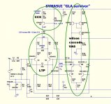
This one is different ,
It uses a blue and red led to reference both the CCS and the VAS's
cascode. (D5/D3/R16) Simple , it also negates tempco and CM distortion.
The LTP is common fare with a more precise offset adjustment (Q1/2 +
R7-11).
The Wilson Cascoded VAS is the winning ticket. Q4/5 + Q9/10 can be
small low voltage (cheep !!) to-92's.
The "wilson" part of the Mirror (Q6) does all the work (acts as a cascode).
On the active side , Q7/8 (another cascode) do the "heavy lifting",
and are a good match for Q6 (A high-Z cascode).
All this is compensated with the Sansui lead/lag/miller "array" (C5/6/7)
C7 sets the pole , C5/6 "tweaks" phase for real good stability margin.
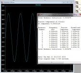
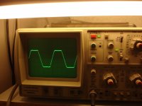
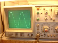
Driving a EF3 with this ... it does 11ppm 1/2 power and only 33 full throttle.
(below 2) .... clipping has only the most minor saturation and is
symmetric within 200mV. (below 3)
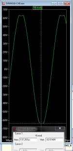
WAY better , by far than the original ... and able to leap tall buildings
in a single waveform 😀 ( 125V p-p with 70V rails ).
OS
Attachments
Last edited:
No, i have put standard red leds, not high efficiency.
Still , go 820R or lower for R13/16 to get within range ... (7-8ma- R17/21).
THEN ..... "trim" vas I by bleeding X amount of that current away by using
33-56K at hawksford LED string (R20).
OS
Thanks OS but i can't understand this"THEN ..... "trim" vas I by bleeding X amount of that current away by using
33-56K at hawksford LED string (R20)."
Do you mean to play with values R19 R20 FROM 33K UP TO 56K?
Or you mean R18?
33-56K at hawksford LED string (R20)."
Do you mean to play with values R19 R20 FROM 33K UP TO 56K?
Or you mean R18?
Last edited:
This one is different
I see, not really a symasym at all. Funny that folks pick that amp apart when it sounds so good.
I see, not really a symasym at all. Funny that folks pick that amp apart when it sounds so good.
No !! The VAS has the same "temperment". Except that it can really
fly. FFT wise ... it also resembles the SYM - but with much less THD.
If you "partied" with it , and drove it ever closer to those rails ....
It DOES (exactly)match the SYM (harmonic wise). At the rails , it just
behaves itself while you overdrive it.
os
Thanks OS but i can't understand this"THEN ..... "trim" vas I by bleeding X amount of that current away by using
33-56K at hawksford LED string (R20)."
Do you mean to play with values R19 R20 FROM 33K UP TO 56K?
Or you mean R18?
I mean the resistor that goes between the hawksford leds. R18 or
R20 could be different from my simulator schema > ips schema.
the hawksford led I is usually 3ma , this is shared current from
the cascode Re's (150R) ... If you get a little more than 8ma at those
R's , increase the LED current to "bleed" more away from the
cascodes. 4.5 - 5ma is what the cascode collectors should see.
OS
Ok i understand this .
Thanks, this is job for tomorrow.
Now i have the rest of test.
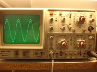
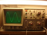
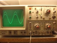
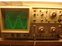
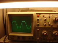
Clipping at 20KHz
1)Inp.=950mV RMS
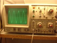
5)Inp=1.5V RMS
6-7)inp. signal down,out signal up(20KHz)
8) same as pict 6-7 two signals superimposed.
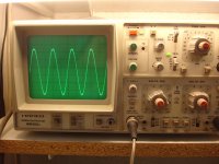
9)30KHz
10)30 KHz signals superimposed
to be continued..
Thanks, this is job for tomorrow.
Now i have the rest of test.
Clipping at 20KHz
1)Inp.=950mV RMS
5)Inp=1.5V RMS
6-7)inp. signal down,out signal up(20KHz)
8) same as pict 6-7 two signals superimposed.
9)30KHz
10)30 KHz signals superimposed
to be continued..
Attachments
-
 DSC07520.JPG585.3 KB · Views: 173
 -
 DSC07519.JPG524 KB · Views: 173
 -
 DSC07518.JPG594 KB · Views: 174
 -
 DSC07517.JPG547.9 KB · Views: 186
 -
 DSC07516.JPG571.6 KB · Views: 176
 -
 DSC07515.JPG514.4 KB · Views: 182
 -
 DSC07514.JPG515.1 KB · Views: 174
 -
 DSC07513.JPG596.5 KB · Views: 176
 -
 DSC07512.JPG615.4 KB · Views: 642
 -
 DSC07509.JPG533.6 KB · Views: 687
Last edited:
the rest
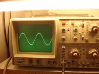
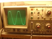
1)40KHz
2)40KHz superimposed
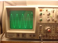
3)60KHz
4)80KHz
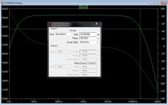
-3db at 2,7 HZ DOWN(Tested at 14v RMS)
-3db at 200KHz UP(Tested at 14v RMS)
1)40KHz
2)40KHz superimposed
3)60KHz
4)80KHz
-3db at 2,7 HZ DOWN(Tested at 14v RMS)
-3db at 200KHz UP(Tested at 14v RMS)
Attachments

Last edited:
Looks like OEM reliability + Superior DIY performance.
Excellent. 🙂 😎
Amp bandwidth would be 3hz-200Khz (-3db) ?
REAL close to the LT sim.
OS
Excellent. 🙂 😎
Amp bandwidth would be 3hz-200Khz (-3db) ?
REAL close to the LT sim.
OS
Thanks OS. This looks Excellent ,congratulations!🙂Looks like OEM reliability + Superior DIY performance.
Excellent. 🙂 😎
OS
Yes ,amplifier tested at 16V RMS OUT. which is stable from 3Hz up to 200KHz. At 2,7 Hz this Vout =11,312V .At 200KHz this Vout=11,312V
(16*0,707=11,312)
Tomorrow i will try these recommended modifications on VAS.
Best Regards.
Thimios.
Last edited:
Thanks OS. This looks Excellent ,congratulations!🙂
Yes ,amplifier tested at 16V RMS OUT. which is stable from 3Hz up to 200KHz. At 2,7 Hz this Vout =11,312V .At 200KHz this Vout=11,312V
(16*0,707=11,312)
Tomorrow i will try these recommended modifications on VAS.
Best Regards.
Thimios.
LT is right on ... 28.5db gain / 2.5hz to 190+Khz (-3db).
PS- drops like a rock at <.5hz-1hz (servo is R/C .2hz )...
OS
Attachments
Last edited:
the rest
1)40KHz
2)40KHz superimposed
3)60KHz
4)80KHz
-3db at 2,7 HZ DOWN(Tested at 14v RMS)
-3db at 200KHz UP(Tested at 14v RMS)
I like this.
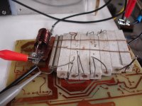
Thimios, what kind of load do you use?

OS,
How fast an oscilloscope are you having to use to test these circuits? What would be a practical range to use on these and other audio circuits?
How fast an oscilloscope are you having to use to test these circuits? What would be a practical range to use on these and other audio circuits?
OS,
How fast an oscilloscope are you having to use to test these circuits? What would be a practical range to use on these and other audio circuits?
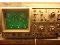
I use A/D PC based setup ..no analog scope (only 10 mhz).
I only use it sparingly , as with good models ... my sims reflect the real world
nearly perfectly (thimios's scope mirrors my LT spice EXACTLY).
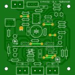
On to the new shat...
Almost done with the symasui .. (below)
kept it small at 76.2 X76.2mm ..
I would suggest to build this .... it "flies".
so simple , yet can do that 125v p-p with the grace of
a 2000$ amp .... 😎 I would prefer this over a badger/
wolverine...
OS
Attachments
Hi OS... can you adopt SMT 1206 parts for the IPS to keep the board size as small as possible? I think this is important if we are going to mount these boards on the back of the case as you suggest.
Hi bimo look here,isn't a luxury load: 8x1R/17WI like this.
Thimios, what kind of load do you use?
I can test again with a RIGOL ds1102 if it is interesting
Attachments
Last edited:
- Home
- Amplifiers
- Solid State
- Slewmaster - CFA vs. VFA "Rumble"