Wow - lots of activity in the last few days. Here are a few comments about various topics that have appeared here recently.
JG buffer power supply
As pointed out by Atupi, it needs a +-V power supply. A wide voltage range will work. I've seen people run this off of two 9v batteries, which is as low as I would like to go. I use +-14.4v but that's just because that happened to be what I got with parts on hand. I used LT1963 regulators but many other regulators would be fine. Power supplies can affect the sound so use what you like and what fits within your budget and the physical space that you have. I haven't done a lot of experimentation but have used LT1085 regulators in other builds with good results. This is DIY - try something else and let us know how it works. Next up on my list to try is the TPS7A4700.
Part selection and the new BOM
I think that there is an emerging consensus on what a new BOM could look like. It appears that JP and I are quite aligned on what we like these days. And I can assure JP that I don't normally put parts on the bottom of the board. That was only done on my experimental board which used a beta version of the V3 dac board. That board didn't have the flexibility of the current board in terms of room and vias for trying different parts, so I had to be creative in mounting parts.
Key changes:
C17 - 1uf X7R MLCC Ceramic capacitor (many possible vendors)
C22 - 470uf 6.3v Panasonic SEPC 6SEPC470
C32 - 1uf Wima MKS2 with 2.5mm lead spacing - MKS0B041000F00KSSD
C35 - you should use either C32 or C35, but not both. If you want to experiment with larger values of Wima MKS2 that only come with 5mm lead spacing then use the C35 location instead of C32. You should not use a value >4.7uf or the sound gets worse.
C4 - 1uf Wima MKS2 with 5mm lead spacing - MKS2-1/50/10 or MKS2-1/63/5T or MKS2C041001F00KSSD
I think it's safe to say that several people have tried these out and found them to be a good reference point.
All the best.
---Gary
If one of you could make a new BOM that would be terrific. I am often away from home and when I am at home I am busy with a new product.
... And I can assure JP that I don't normally put parts on the bottom of the board. That was only done on my experimental board which used a beta version of the V3 dac board. That board didn't have the flexibility of the current board in terms of room and vias for trying different parts...
---Gary
Gary/Jean-Paul,
Why is it bad to mount from underneath other than cosmetics? I'm thinking of trying wima 10uf for C8-C13-C21 and I could be wrong, but I think those will still need to be mounted below. The sal-rpm fit perfectly there, of course, and I might just stick with those unless you still prefer the available films and polymers which are not an exact fit, but may be superior. Thanks.
I think it's only the cosmetics that are a problem. It doesn't look very professional. But it works just fine. My experience with C8-C13-C21 was that Wima MKS2 caps weren't much of an improvement over polymer or SAL-RPM caps but they weren't worse either. So in my recent builds, I ended up using polymer caps for C8 and C13 and SAL-RPM for C21. Despite JP's belief in my systematic approach to parts swapping, in this case I just put in what seemed like interesting parts. My earlier experiments had said there wasn't a large difference from these components so I put in "good enough" quality parts and focused on other things.
So there's room for you to jump in, see how you like them, and report on your findings.
All the best.
---Gary
Hi,
It seems the Deming wheel maid one more turn with the last list of Gary and with enough significant progress to be posted on the first post by the OP or puted in the official BOM:
C17 - 1uf X7R MLCC Ceramic capacitor (many possible vendors)
C22 - 470uf 6.3v Panasonic SEPC 6SEPC470
C32 - 1uf Wima MKS2 with 2.5mm lead spacing - MKS0B041000F00KSSD
C35 - you should use either C32 or C35, but not both. If you want to experiment with larger values of Wima MKS2 that only come with 5mm lead spacing then use the C35 location instead of C32. You should not use a value >4.7uf or the sound gets worse.
C4 - 1uf Wima MKS2 with 5mm lead spacing - MKS2-1/50/10 or MKS2-1/63/5T or MKS2C041001F00KSSD
Maybe we can continue with an other cycle of mods ?! The more cycles the more subtiles to go to personal flavor (or the fanatic road) we will go...
I have some questions before new test on the second PCB i'm waiting for :
Gary, JP, others :
- did you try stock PEN caps technologie instead MKT from Wima ?
Or :
- Like the "softer" green plastic MKT (don't remenber the brand)
- Like the "blue" MKT from Philips which are more analytic but colder...
- Like some others Vishay 1832, EPCOS...
About the smd MLCC X7R caps, is there any difference for the ears when smd COG ceramic are used ?
- any test with PEN smd caps, or others film smd technologies ?
- Polystyren for C4 ?
- C9/C30 : smd film cap ("Curyman way")
- C36 (=C22 bypass) : another value like 4,7 uf (= 1% of 470 uF -C22 SEPC) to avoid theoric resonances.
- Main Power supply PCB : faster bridge at B1 (bad ref also on the offical BOM)?
What Gary said about C8-C13-C21 is interresting : waste of time to investigate more ?
Don't hesitate to trash the bad ideas... or say if already tested.
Thanks Gary for the new list, (have seen you used no Panasonic FC alum caps on your own JG...buffer, nore KZ Muse...)
Mes meilleurs egalement,
Eldam
Eldam,Maybe we can continue with an other cycle of mods ?! The more cycles the more subtiles to go to personal flavor (or the fanatic road) we will go...
I really admire your enthusiasm. It's great that you are so excited and willing to try so many things. I have already built 5 of these Subbu/JP DACs, so I am close to the end of my willingness to experiment. I have 2 original V2.6 DACs, 1 experimental beta V3 DAC, and 2 official V3 DACs. The original V2.6 DACs are complete with JG buffers and running fine. I will do another experiment with different 5v power supply and I may try out JP's suggest of 1uf capacitor for the Vneg generator. Other than that, I am done experimenting. I just want to build up the remaining V3 DACs into finished boxes and finish this saga. It's time for me to move on to other DIY adventures.
The answer to all your questions is no - I didn't try any of those with the following exceptions.IGary, JP, others :
- did you try stock PEN caps technologie instead MKT from Wima ?
Or :
- Like the "softer" green plastic MKT (don't remenber the brand)
- Like the "blue" MKT from Philips which are more analytic but colder...
- Like some others Vishay 1832, EPCOS...
About the smd MLCC X7R caps, is there any difference for the ears when smd COG ceramic are used ?
- any test with PEN smd caps, or others film smd technologies ?
- Polystyren for C4 ?
- C9/C30 : smd film cap ("Curyman way")
- C36 (=C22 bypass) : another value like 4,7 uf (= 1% of 470 uF -C22 SEPC) to avoid theoric resonances.
- Main Power supply PCB : faster bridge at B1 (bad ref also on the offical BOM)?
What Gary said about C8-C13-C21 is interesting : waste of time to investigate more ?
Don't hesitate to trash the bad ideas... or say if already tested.
Thanks Gary for the new list, (have seen you used no Panasonic FC alum caps on your own JG...buffer, nore KZ Muse...)
C36 - the bypass of C22. I used 10uf 25v X7R ceramic caps. It certainly did no harm and may be a small improvement. I didn't spend a lot of time comparing.
Regarding the quality of the main bridge - I used the stock part. I did use Fairchild Stealth soft recovery diodes for the JG buffer power supply. But more importantly, I used snubbers on all the transformer secondaries, which makes the power supply insensitive to the quality of the diodes. See this thread http://www.diyaudio.com/forums/power-supplies/243100-simple-no-math-transformer-snubber-using-quasimodo-test-jig.html for a very interesting discussion on snubbers and a piece of test equipment to help calculate optimal snubbers. The value of snubbers isn't that critical so I just use the same value of snubber for each transformer secondary and didn't worry about optimizing it.
Finally, you made a comment about the capacitors I use in my JG buffer. I don't think that I ever mentioned that, so I'm not sure I know what you mean.
All the best,
--Gary
power supply experiments
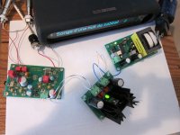
All the traffic of the last few days inspired me to pull out one of my V3 DACs and do some experiments on the 5V power supply. I normally use the standard 5V power supply that Subbu and JP offered with the V3 DAC based on the LM723 low noise regulator chip. For comparison, I bought an inexpensive regulator board based on the LT1764. It's built by a company called Audiowind and is their model A270. You can find the schematic here http://www.audiowind.com/pdf/A-270.pdf and it's available on ebay for around $15-$20 including shipping from Hong Kong. Search for "VERY LOW NOISE <40μV Adjustable Voltage Regulator" on ebay and you'll find a few vendors selling it. It's not complete like the Subbu power supply. It doesn't have a transformer or bridge rectifier, so for this comparison I tapped power from the Subbu power supply. Initially I got power right after the bridge rectifier at the terminals for C1. Both the Subbu supply and the LT1764 don't have many hours on them, so consider all my comments about sound quality as preliminary.
First comparison - Subbu PS vs. LT1764 tapped off of C1
This was pretty easy. The LT1764 seemed a bit washed out and harsh and not as nice to listen to. It had certain good qualities but overall, I found myself wanting to quickly switch back to the Subbu PS.
After this quick result, I was scratching my head wondering why the LT1764 didn't sound better. It occurred to me that the extra LCL filtering in the Subbu PS (C1-L1-C3) might help filter out some high frequency noise which could cause problems with a feedback regulator like the LT1764. So I rewired things so that I was getting power for the LT1764 at C3, which means after the LC filter.
Second comparison - Subbu PS vs. LT1764 tapped off of C3
With this change, things changed and the LT1764 was preferred. It had much deeper bass and seemed to have a more three dimensional soundstage. In comparison, the Subbu PS sounded very smooth but a bit flat and seemed to miss some of the deepest bass. I was surprised at the difference.
I recall several people saying they got a big difference using a Salas shunt regulator for this 5v power and I now see that they may be onto something. While the Subbu PS is very good, it does appear that there is room for improvement.
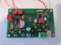
Attached are a couple of pictures showing my temporary hookup. V3 DAC is fed from a Squeezebox 2 which of course I've tweaked. I can switch from one power supply to the other in less than a minute, so it's possible to do relatively quick comparison. And for those curious to see what my V3 build looks like, I included a close up of my V3 DAC so you can see what I'm listening to.
All the best.
---Gary
All the traffic of the last few days inspired me to pull out one of my V3 DACs and do some experiments on the 5V power supply. I normally use the standard 5V power supply that Subbu and JP offered with the V3 DAC based on the LM723 low noise regulator chip. For comparison, I bought an inexpensive regulator board based on the LT1764. It's built by a company called Audiowind and is their model A270. You can find the schematic here http://www.audiowind.com/pdf/A-270.pdf and it's available on ebay for around $15-$20 including shipping from Hong Kong. Search for "VERY LOW NOISE <40μV Adjustable Voltage Regulator" on ebay and you'll find a few vendors selling it. It's not complete like the Subbu power supply. It doesn't have a transformer or bridge rectifier, so for this comparison I tapped power from the Subbu power supply. Initially I got power right after the bridge rectifier at the terminals for C1. Both the Subbu supply and the LT1764 don't have many hours on them, so consider all my comments about sound quality as preliminary.
First comparison - Subbu PS vs. LT1764 tapped off of C1
This was pretty easy. The LT1764 seemed a bit washed out and harsh and not as nice to listen to. It had certain good qualities but overall, I found myself wanting to quickly switch back to the Subbu PS.
After this quick result, I was scratching my head wondering why the LT1764 didn't sound better. It occurred to me that the extra LCL filtering in the Subbu PS (C1-L1-C3) might help filter out some high frequency noise which could cause problems with a feedback regulator like the LT1764. So I rewired things so that I was getting power for the LT1764 at C3, which means after the LC filter.
Second comparison - Subbu PS vs. LT1764 tapped off of C3
With this change, things changed and the LT1764 was preferred. It had much deeper bass and seemed to have a more three dimensional soundstage. In comparison, the Subbu PS sounded very smooth but a bit flat and seemed to miss some of the deepest bass. I was surprised at the difference.
I recall several people saying they got a big difference using a Salas shunt regulator for this 5v power and I now see that they may be onto something. While the Subbu PS is very good, it does appear that there is room for improvement.
Attached are a couple of pictures showing my temporary hookup. V3 DAC is fed from a Squeezebox 2 which of course I've tweaked. I can switch from one power supply to the other in less than a minute, so it's possible to do relatively quick comparison. And for those curious to see what my V3 build looks like, I included a close up of my V3 DAC so you can see what I'm listening to.
All the best.
---Gary
Attachments
Gary. I'm interested in what value for C35. Is that a 4.7uf? Also do you still recommend the 3.3/0.1uf parallel for C4? Thanks. Very interesting.
Freeman,Gary. I'm interested in what value for C35. Is that a 4.7uf? Also do you still recommend the 3.3/0.1uf parallel for C4? Thanks. Very interesting.
Yes - C35 is a 4.7uf Wima MKS2 as I have suggested for a long time. At some point I want to try a smaller value such as the 1uf Wima that JP likes.
For C4, I'm still using 3.3 in parallel with 0.1uf. Theoretically, I believe that 1uf should be a big enough capacitor here but I haven't done the comparison. Eldam has tried 1uf and finds it a big step up from 0.1uf alone. I'd be interested in hearing results from others who experiment with values between 1uf and 3.3uf.
In an earlier post you talked about a JP DAC vs. a GaryB DAC but I think neither one really reflects what JP or I are listening to. Just for the record here is where the DAC pictured above differs from the BOM. This is the real GaryB DAC, at least as of 3/9/14. No guarantees it will be the same in the future. I've already discussed the changes that I think are most significant and worth trying. The rest of the changes are things I've changed because I think they should be an improvement but I haven't rigorously evaluated their benefit.
C2 - BOM UCC 100uf 16v NPCAP; GaryB Nichicon 270uf 16v FP
C3, C18 - BOM UCC 100uf 16v NPCAP; GaryB UCC 220uf 6.3v NPCAP; I've also used Nichicon 220uf 6.3v FP caps here with no noticeable difference
C5, C7, C19, C20 - BOM 4.7uf Tantalum or 1uf X7R MLCC; GaryB 10uf X7R MLCC
C8, C13 - BOM Elna 100uf 35v Silmic; GaryB 10uf 25v Nichicon LF
C22 - GaryB 470uf 16v Nichicon FP, eventually I'll try a 470uf 6.3v Panasonic SEPC to see if there is a difference
C36 - BOM 1uf X7r; GaryB 10uf X7R MLCC
C4 - BOM 0.1uf X7R MLCC or 0.1uf polyester; GaryB 0.1uf X7R MLCC + 3.3uf Wima MKS2 polyester
C35 - GaryB 4.7uf Wima MKS2 polyester
C17 - BOM initially 4.7uf Tantalum, recently changed to 1uf X7R MLCC; GaryB 0.22uf COG ceramic because that's what was available at the time, should be similar to the 1uf X7R MLCC
Q2 - BOM Abracon 50Mhz 3.3v crystal oscillator; GaryB Epson XG-1000CA 50Mhz saw oscillator
I apologize in advance if all these changes confuse people. I am not recommending that people adopt all these changes. I've already discussed the changes that I think are important and worth adopting. The rest of the changes are just that - things I did differently but aren't yet clearly an improvement. I just thought that people would be curious to know what I've done.
---Gary
I have built a couple versions of the Salas Shunt 5V supply point-to-point, all from parts I had in the parts bin. Let me know if you are interested in trying one out or build yourself. Let me know.All the traffic of the last few days inspired me to pull out one of my V3 DACs and do some experiments on the 5V power supply. I normally use the standard 5V power supply that Subbu and JP offered with the V3 DAC based on the LM723 low noise regulator chip. For comparison, I bought an inexpensive regulator board based on the LT1764. It's built by a company called Audiowind and is their model A270. You can find the schematic here http://www.audiowind.com/pdf/A-270.pdf and it's available on ebay for around $15-$20 including shipping from Hong Kong. Search for "VERY LOW NOISE <40μV Adjustable Voltage Regulator" on ebay and you'll find a few vendors selling it. It's not complete like the Subbu power supply. It doesn't have a transformer or bridge rectifier, so for this comparison I tapped power from the Subbu power supply. Initially I got power right after the bridge rectifier at the terminals for C1. Both the Subbu supply and the LT1764 don't have many hours on them, so consider all my comments about sound quality as preliminary.
First comparison - Subbu PS vs. LT1764 tapped off of C1
This was pretty easy. The LT1764 seemed a bit washed out and harsh and not as nice to listen to. It had certain good qualities but overall, I found myself wanting to quickly switch back to the Subbu PS.
After this quick result, I was scratching my head wondering why the LT1764 didn't sound better. It occurred to me that the extra LCL filtering in the Subbu PS (C1-L1-C3) might help filter out some high frequency noise which could cause problems with a feedback regulator like the LT1764. So I rewired things so that I was getting power for the LT1764 at C3, which means after the LC filter.
Second comparison - Subbu PS vs. LT1764 tapped off of C3
With this change, things changed and the LT1764 was preferred. It had much deeper bass and seemed to have a more three dimensional soundstage. In comparison, the Subbu PS sounded very smooth but a bit flat and seemed to miss some of the deepest bass. I was surprised at the difference.
I recall several people saying they got a big difference using a Salas shunt regulator for this 5v power and I now see that they may be onto something. While the Subbu PS is very good, it does appear that there is room for improvement.
Attached are a couple of pictures showing my temporary hookup. V3 DAC is fed from a Squeezebox 2 which of course I've tweaked. I can switch from one power supply to the other in less than a minute, so it's possible to do relatively quick comparison. And for those curious to see what my V3 build looks like, I included a close up of my V3 DAC so you can see what I'm listening to.
All the best.
---Gary
Cheers,
Hi GarryB,
Thank you for all these inputs.
I can understand you about mooving for new DIY adventures !
I will stop with my second PCB. I 'm waiting 2 spidf W8004 pcb from Sure Electronics China (10 days and no news for the moments) to play with some old chips I have like TDA 15x, AD18xx, PCM56...
I will sure it will be not better than a good design with a good pcb TAILORED for it with smd parts... Sometimes improving a good design for its own taste is a better narrow path.
I'm aware the deeper you dive in details (like with caps) the smaller are the improvements or the more you go only to a personal flavor setup. It's very intteresting to understand the improvement process Subbu/JP had for their final setup beyond the tests with scope. We saw themselves important differences exist between two close caps. With my system I can hear it with C18 and just can no hear the FP cap you use yourself for C18. I saw many fellows use these expensive Nichicon FP cap at C18 and wanted just to share how bad it was for me (not just a question of flavor here IHMO !).
Always interrested by your inputs, I don't forgett we have close Squeezebox source, but your with more serious improvement (I work on that beyond my own test don't show improvements with another powersupplies... but they were simple one, (LT1084...serie)
About the caps of the JG buffer, I just mentionned a photograph you post and I don't recognize the Panasonic FC caps advised for it. May be I did a mistake ? An another fellow's JG buffer/Subbu photograph ?
Finally thank you for sharing Gary.🙂
Last edited:
If one of you could make a new BOM that would be terrific. I am often away from home and when I am at home I am busy with a new product.
I can recognise here both the DIY man and marketing man 😀
What about your new product ? Is it your DIY plane with a DAC indside ? Jetman... I can recognize you 😛 ... Oh no he is from Switserland !
JP, have time to put the official aproved Gary mods in an xls if it helps Subbu, you and these Dac communauty. But if it's the last revision maybe these revision can be publisged in first OP page. As you want...
regards
Freeman,
Yes - C35 is a 4.7uf Wima MKS2 as I have suggested for a long time. At some point I want to try a smaller value such as the 1uf Wima that JP likes.
For C4, I'm still using 3.3 in parallel with 0.1uf. Theoretically, I believe that 1uf should be a big enough capacitor here but I haven't done the comparison. Eldam has tried 1uf and finds it a big step up from 0.1uf alone. I'd be interested in hearing results from others who experiment with values between 1uf and 3.3uf.
In an earlier post you talked about a JP DAC vs. a GaryB DAC but I think neither one really reflects what JP or I are listening to. Just for the record here is where the DAC pictured above differs from the BOM. This is the real GaryB DAC, at least as of 3/9/14. No guarantees it will be the same in the future. I've already discussed the changes that I think are most significant and worth trying. The rest of the changes are things I've changed because I think they should be an improvement but I haven't rigorously evaluated their benefit.
C2 - BOM UCC 100uf 16v NPCAP; GaryB Nichicon 270uf 16v FP
C3, C18 - BOM UCC 100uf 16v NPCAP; GaryB UCC 220uf 6.3v NPCAP; I've also used Nichicon 220uf 6.3v FP caps here with no noticeable difference
C5, C7, C19, C20 - BOM 4.7uf Tantalum or 1uf X7R MLCC; GaryB 10uf X7R MLCC
C8, C13 - BOM Elna 100uf 35v Silmic; GaryB 10uf 25v Nichicon LF
C22 - GaryB 470uf 16v Nichicon FP, eventually I'll try a 470uf 6.3v Panasonic SEPC to see if there is a difference
C36 - BOM 1uf X7r; GaryB 10uf X7R MLCC
C4 - BOM 0.1uf X7R MLCC or 0.1uf polyester; GaryB 0.1uf X7R MLCC + 3.3uf Wima MKS2 polyester
C35 - GaryB 4.7uf Wima MKS2 polyester
C17 - BOM initially 4.7uf Tantalum, recently changed to 1uf X7R MLCC; GaryB 0.22uf COG ceramic because that's what was available at the time, should be similar to the 1uf X7R MLCC
Q2 - BOM Abracon 50Mhz 3.3v crystal oscillator; GaryB Epson XG-1000CA 50Mhz saw oscillator
I apologize in advance if all these changes confuse people. I am not recommending that people adopt all these changes. I've already discussed the changes that I think are important and worth adopting. The rest of the changes are just that - things I did differently but aren't yet clearly an improvement. I just thought that people would be curious to know what I've done.
---Gary
How does the sound change/Improve with this changes?
side by side by C18
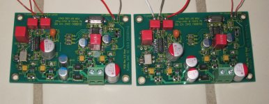
The only difference between my two V3 DACs is the cap used for C3, C18. Nichicon FP in one and UCC NPCAP in the other. So I'm set up to do a direct comparison of the difference between these 2 caps. Both DACs have all the other changes that I described in my earlier note. So this morning I swapped DACs and couldn't hear much if any difference. The Nichicon FP version sounds very good as did the UCC NPCAP version.
No capacitor has a sound of its own. I verified this for myself. I can stick both capacitors in my ears and hear nothing! Excuse my little joke.
But the capacitors do interact with the rest of the circuit and depending upon the rest of the parts used then one may or may not hear a difference.
As I have said a few times, I have already pointed out the changes that I found significant enough for others to follow. The rest of the changes are things that I tried and thought should be better. I added them to one DAC and thought they were better in a small way but not important enough to justify changing the BOM. For consistency of other comparisons, I put these changes in both of my V3 DACs, so that when I did want to make rigorous comparisons I had a consistent comparison. I haven't done a rigorous comparison of the cumulative effect of all these changes. Perhaps I will listen to my beta V3 board, which is missing some of these changes, to see if there is anything from the cumulative set of changes.
---Gary
We saw themselves important differences exist between two close caps. With my system I can hear it with C18 and just can no hear the FP cap you use yourself for C18. I saw many fellows use these expensive Nichicon FP cap at C18 and wanted just to share how bad it was for me (not just a question of flavor here IHMO !)
The only difference between my two V3 DACs is the cap used for C3, C18. Nichicon FP in one and UCC NPCAP in the other. So I'm set up to do a direct comparison of the difference between these 2 caps. Both DACs have all the other changes that I described in my earlier note. So this morning I swapped DACs and couldn't hear much if any difference. The Nichicon FP version sounds very good as did the UCC NPCAP version.
No capacitor has a sound of its own. I verified this for myself. I can stick both capacitors in my ears and hear nothing! Excuse my little joke.
But the capacitors do interact with the rest of the circuit and depending upon the rest of the parts used then one may or may not hear a difference.
You are right, there was a picture of one of my JG buffers posted a long time ago. I'm just surprised that anyone noticed details like that. The circuit used for the JG buffer is not very sensitive to the power supply so I have not done much work comparing capacitors. I don't think the type matters too much.About the caps of the JG buffer, I just mentionned a photograph you post and I don't recognize the Panasonic FC caps advised for it. May be I did a mistake ? An another fellow's JG buffer/Subbu photograph ?
Ryssen,How does the sound change/Improve with this changes?
As I have said a few times, I have already pointed out the changes that I found significant enough for others to follow. The rest of the changes are things that I tried and thought should be better. I added them to one DAC and thought they were better in a small way but not important enough to justify changing the BOM. For consistency of other comparisons, I put these changes in both of my V3 DACs, so that when I did want to make rigorous comparisons I had a consistent comparison. I haven't done a rigorous comparison of the cumulative effect of all these changes. Perhaps I will listen to my beta V3 board, which is missing some of these changes, to see if there is anything from the cumulative set of changes.
---Gary
Attachments
Hi Gary, just one more question before I place my order for my final version. How critical is C21? I think I remember you saying at one point you found little difference in polymer and sal-rpm. Thanks, Gary.
All the traffic of the last few days inspired me to pull out one of my V3 DACs and do some experiments on the 5V power supply. I normally use the standard 5V power supply that Subbu and JP offered with the V3 DAC based on the LM723 low noise regulator chip. For comparison, I bought an inexpensive regulator board based on the LT1764. It's built by a company called Audiowind and is their model A270. You can find the schematic here http://www.audiowind.com/pdf/A-270.pdf and it's available on ebay for around $15-$20 including shipping from Hong Kong. Search for "VERY LOW NOISE <40μV Adjustable Voltage Regulator" on ebay and you'll find a few vendors selling it. It's not complete like the Subbu power supply. It doesn't have a transformer or bridge rectifier, so for this comparison I tapped power from the Subbu power supply. Initially I got power right after the bridge rectifier at the terminals for C1. Both the Subbu supply and the LT1764 don't have many hours on them, so consider all my comments about sound quality as preliminary.
First comparison - Subbu PS vs. LT1764 tapped off of C1
This was pretty easy. The LT1764 seemed a bit washed out and harsh and not as nice to listen to. It had certain good qualities but overall, I found myself wanting to quickly switch back to the Subbu PS.
After this quick result, I was scratching my head wondering why the LT1764 didn't sound better. It occurred to me that the extra LCL filtering in the Subbu PS (C1-L1-C3) might help filter out some high frequency noise which could cause problems with a feedback regulator like the LT1764. So I rewired things so that I was getting power for the LT1764 at C3, which means after the LC filter.
Second comparison - Subbu PS vs. LT1764 tapped off of C3
With this change, things changed and the LT1764 was preferred. It had much deeper bass and seemed to have a more three dimensional soundstage. In comparison, the Subbu PS sounded very smooth but a bit flat and seemed to miss some of the deepest bass. I was surprised at the difference.
I recall several people saying they got a big difference using a Salas shunt regulator for this 5v power and I now see that they may be onto something. While the Subbu PS is very good, it does appear that there is room for improvement.
Attached are a couple of pictures showing my temporary hookup. V3 DAC is fed from a Squeezebox 2 which of course I've tweaked. I can switch from one power supply to the other in less than a minute, so it's possible to do relatively quick comparison. And for those curious to see what my V3 build looks like, I included a close up of my V3 DAC so you can see what I'm listening to.
All the best.
---Gary
Coincidentally I use LT1764A on another project. It is good but it is no match for LM723 in terms of noise. However, it can deliver 3 A without external parts.
I thought earlier to replace the coils in V3 for higher current rated parts as they are not very low in DC resistance. You could try the 47 µH for a change. I wonder how the LM723 will turn out then. Purpose of the coils seems clear to you 🙂
The only difference between my two V3 DACs is the cap used for C3, C18. Nichicon FP in one and UCC NPCAP in the other. So I'm set up to do a direct comparison of the difference between these 2 caps. Both DACs have all the other changes that I described in my earlier note. So this morning I swapped DACs and couldn't hear much if any difference. The Nichicon FP version sounds very good as did the UCC NPCAP version.
No capacitor has a sound of its own. I verified this for myself. I can stick both capacitors in my ears and hear nothing! Excuse my little joke.
But the capacitors do interact with the rest of the circuit and depending upon the rest of the parts used then one may or may not hear a difference.
---Gary
Thanks Garry, yes know that, it's not magic ! Ben oui, it interacts whith eachothers...
I don't talk about the sound of capacitor 😕. It's to write shorter. Understand I talk about a capacitor on a known PCB, with known capacitors around !
With your two photograph I try both with C18/C22 : left picture was better but ultimatly it was far better with the same C18 cap of the left photographs but with SEPC instead FP at C22 as you advised : more fleshy, more softness, no lake of details and not harchness on attack in the mid-high (here I suspect maybe resonances? FP has ESR < 10 mohms -not sure of the scale- maybe the cause of resonance; I 'm asking of the utility of the bypass C36 1uF X7R with the FP ? maybe the problem was here with my listening test... don't know).
But as you said there many interactions : the source, the ears, the speakers, the quality of electricity line. Well after all people are free to do what they want, here the BOM for me was just allright with the OSCON SEPC (470uF/16V). and better than all my better test; Maybe a better tonal with C18 and a 33/16 V BG N but with the price of less resolution than the BOM one. I go back with the one (left photograph) of the BOM at C18 at the end.
I have to said I find strange you don't hear difference between the two photographs... but I suspect you will tell me that photographs don't make sound by themselves 😉
Well i have to work more on my Duet streamer, because I can hear many differences with different SPIDF 0,5 m cable. I surmise they have not sound by themselves as well ! I will follow your advise (that you PM me) about a more stable powersupply...
sad you are so far not to hear by yourself !
regards
Last edited:
about a more stable powersupply...
Interesting, more stable than which power supply ? The LM723 one is pretty stable AFAIK.
I wonder if a coil with lower DC resistance would make a difference. The DC resistance of the BOM L1 is only 10mOhm. That should not limit current too much. For the LT1764, adding the coil before the regulator improved the sound and did not degrade the bass, so it seems somewhat unlikely that the coil is responsible for the difference. I do agree it is a surprising result.I thought earlier to replace the coils in V3 for higher current rated parts as they are not very low in DC resistance. You could try the 47 µH for a change. I wonder how the LM723 will turn out then. Purpose of the coils seems clear to you 🙂
---Gary
Interesting, more stable than which power supply ? The LM723 one is pretty stable AFAIK.
HI JP
I was talking here about a private discussion between GARY and I about the powersupply of our squeezeBox.
As I already said I use the genuine PS with the 2200 uF but without the 0,1 uf MKT cap just after a bridge. I can not just understand here why we have to pull faster on a modulate current with its imperfection, as i would prefer put here a more little value for C1 than C2. i would put the 0,1 uF after the coil... but think it doesn't matter because the two smd caps of 1 uF. maybe it's a theory I don't understand also. like to learn.
Any input about my smd questions above to you ?
I saw after few readings than it's noy easy to find COG smd > 0.68 uF, Maybe the too low ESR of COG smd can be a problem near the ES Dac chip ?
Any advantage here on some PEN SMD or film smd caps instead X7R ? Let me know for culture which is better (appart short trace) about digital decoupling (I already understand about what you said for LDO regs an read the datasheet of Micrel after).
(Why for R7 a ferrite bead of the same value is not better or can not be heard ? You know all the silly question I have. But it's never a criticism of your work...I just don't understand some things.)
thanks
Last edited:
- Home
- Vendor's Bazaar
- Modifying the Subbu V3 DAC