I was thinking of a small coax, with only midwoofers 'synergy-mounted'
but I'm not sure it really would be a synergy
That makes perfect sense, and I can see why you could take that approach. It would simplify the design, yet still allow for the 3-way configuration.
I hope you don't listen to any "tape" recordings for I'm certain you will find too much "masking".
...Just glad you haven't "boxed" yourself in to a final design.
tomlang, you are a punny man! I just hope that I can "seal" the deal, and the ideas "stick" 😉
I tried the cardboard approach in my Hobohorn, and it worked on mids above 600Hz, although wood turned out better. For the midbass horn (130-600Hz) the difference between paper and wood was too large. The paper midbass horn told me nothing of what the wooden version eventually sounded like.
I would strengthen the cardboard with paint or plaster to have a more solid midbass horn.
Thanks for the advice - I have a LOT of thick cardboard (the stuff I've used here was from a large, but relatively thin panel) that I can brace/reinforce the panels on the outside. I don't intend on taking too long to move on to the wood horn though.
Synergy holes are fairly close to the source which makes them potentially a problem. You can make them small with the right driver. Hiding them in the corners of a square horn can help (although the throat won't be matched to a round driver) . You could also consider Tom Danleys suggested port shape.
The goal would be to put the ports far enough from the compression driver that the waves within its band can at least begin to launch before reaching the ports. The mids would want to be such a distance from the tweeter throat that it creates a null a little above the crossover.
In the case of my spherical OS there were imperfections in the profile as I'd built it by hand, initially up to +/- 5mm toward the end (less toward the throat). A few times I spent a half an hour sanding the ridges and filling the dips, and each time the sound became more clean. Even polishing with finer paper imparted a smoothness to the sound.
The further the problem was from the driver, the lower the frequencies that were involved and the less obvious the problem was. Similarly, I couldn't confidently notice a change regarding the floor and ceiling reflections when changing from ellipsoidal OS.
Interesting. So, if I aimed for a null point of say 1200 or 1500Hz, would that sound far enough away from the 1000Hz 'crossover'?
At any rate, that would give distances of:
1130/1200*12=11.3 inches
1130/1500*12=9.04 inches
For some reason, I thought the goal with Synergy horns was to get the ports as close to the throat of the horn as possible...definitely mistaken on that!
Yes you did!
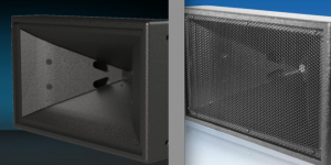
I'll re-post the correct way to do it again (hint- it is the one on the left) 🙂.
To get a sense of the size of the holes for the 8", note that there are two visible mounting screws on the mouth side just before the second part off the horn.
Note that the two frankfurter shaped exit holes are in a low pressure part of the horn, where they will have the least effect on the HF response.
Art
Thanks Art - I'd obviously had a severe mental block and 'forgot' the design that Danley and everyone else here uses! 😀
What governs the shape of the ports? Ap1 and Lpt (in HornResp) give us the area and depth, and given the half-circle approach (as identified by panjilaras), do I just scale that shape to match?
T...I thought the goal with Synergy horns was to get the ports as close to the throat of the horn as possible...
the SH95HO you refer to does indeed use 2x 8" mids with rather big port holes ... but also a 1.4" tweeter

port holes may not look like very close to the tweeter
but I'm sure the two 8" mids are mounted closest possible
and is probably what leads to port placing, more or less
I don't understand your question: "do I just scale that shape to match?", both the SH-95 and the SH-95 HO use different 8" drivers, but what looks like pretty similar port hole area.Thanks Art - I'd obviously had a severe mental block and 'forgot' the design that Danley and everyone else here uses! 😀
What governs the shape of the ports? Ap1 and Lpt (in HornResp) give us the area and depth, and given the half-circle approach (as identified by panjilaras), do I just scale that shape to match?
We don't know what volume modification arrangements (if any) are done in the throat chamber, VTC in Hornresp terms.
A single circular port hole simply would mess up the horn wall (and cause more HF problems) more than two semicircular shaped ports, so the area of a single port is divided between the two, and located as close to the HF driver without causing too much ripple in response due to "holes in the throat".
A virtual single point source is not realized without some compromises 😉.
Art
Attachments
Last edited:
I don't understand your question: "do I just scale that shape to match?"
...
A virtual single point source is not realized without some compromises 😉.
Art
It wasn't a particularly intuitive question, sorry. What I was thinking was to take the shape of a particular area, and then proportionally scale that shape up (or down) to match the area of the port I'd need...imagine zooming in or out on something, as a visual reference.
I hope that makes sense!
Ah, compromises! Sadly, the real world gets to us in the end 😉
So:
Code:
Pi	3.1415926536
Area	20.2	cm squared
	6.4298597009
Radius	2.5357168022	cm
Diameter	5.0714336044	cm
If I make a circle of around 5.1cm in diameter, and then cut it in half, and put half on each side (22.96cm from the throat, or 9.04 inches for 1500Hz), that starts to get me close to what needs to be done.
It does look like from those pictures that there's a bit of refinement that goes into the the actual port shape. It almost looks like the teardrop shape would force the air forwards (to the mouth of the horn), rather than across the horn, and maybe that different angle of air pressure helps with the high frequencies too...helping them along, rather than being a column-like barrier.
But of course that's only a guess!
If I make a circle of around 5.1cm in diameter, and then cut it in half, and put half on each side ...
😉
Sound waves do travel in air, but "forcing air" is not a good idea in horn design 🙂.It almost looks like the teardrop shape would force the air forwards (to the mouth of the horn), rather than across the horn, and maybe that different angle of air pressure helps with the high frequencies too...helping them along, rather than being a column-like barrier.
But of course that's only a guess!
My guess is the port shape leaves the most horn wall intact in the critical throat area for the required port area for the rather large (by Synergy standards) cone driver.
What gave you the idea you want the port 22.96cm from the throat, or 9.04 inches for 1500Hz ?
Do either of the DSL models (using an even lower crossover) look like they are even half that distance to you?
Art
Last edited:
What gave you the idea you want the port 22.96cm from the throat, or 9.04 inches for 1500Hz ?
Do either of the DSL models (using an even lower crossover) look like they are even half that distance to you?
AllenB's observation on the previous page:
The goal would be to put the ports far enough from the compression driver that the waves within its band can at least begin to launch before reaching the ports. The mids would want to be such a distance from the tweeter throat that it creates a null a little above the crossover.
So what I did was to take the lowest frequency (plus a little bit) of the compression driver, and find the wavelength of that frequency.
To answer your rhetorical question though Art, no 🙂 I would have guessed at either half or a quarter of a particular wavelength, if any! 'My' ports wouldn't even be lined up under the cone of the driver on my photo!
Hornresp would be your friend here.
I agree. I'm over-thinking things, but I could well be mis-interpreting a lot of input that's been given on this thread, so my errors I suppose are through trying to make sense of the proportions, and why it works.
If I could afford a couple of thousand dollars for some Danley SM60-Fs I'd probably just go any buy them at this point, but as we can see in this thread my budget allowed me a couple of thousand cents instead... 🙄
Last edited:
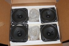
If I could afford a couple of thousand dollars for some Danley SM60-Fs I'd probably just go any buy them at this point, but as we can see in this thread my budget allowed me a couple of thousand cents instead... 🙄
got these from two older stereo TV 🙂
sounds weird, but maybe it could be cheaper for you to build 3way instead of 2way

Attachments
The critical region for the tweeter is going to be related to the perimeter of a cross section of the horn, whereas the mid null will be related to axial length. The horn angle becomes a variable.
This is approximately how I intend to do the midbass. The cutoff frequencies are 140Hz and 60Hz. Crossover between them should be 300Hz give or take an octave. I'm not sure how low they will go but if I could take them to 60Hz I'll be happy. Room width is 12'.I look forward to seeing the updates!
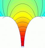
Both horns use LeCleach profiles. The upper bass horns use the mid horn walls and potentially each other at lower frequencies and are longer than shown here, using the floor as a ground plane and being rolled back until the front wall.
Attachments
Is it possible to make the wall between upper/lower bass to be semipermeable, allowing the lower frequencies through while the upperbass horn sees the boundry?
How do you plan on making the phaseplug for the upperbass horn? I would love one of those to experiment with. If you make the 3D model I may be able to get i CNCd or 3D-printed.
How do you plan on making the phaseplug for the upperbass horn? I would love one of those to experiment with. If you make the 3D model I may be able to get i CNCd or 3D-printed.
Last edited:
The lower horns are intended to use the mid walls in reverse as the start of their mouth (come around the back of them and continue around the front). The effective size of the mouth is probably comparable to the size of the room, but it isn't shown in the drawing (it needs to be visualised..considering the LeCleach propagation concept as below). To a degree I've been seeing them as a single horn, and at their higher frequencies the lower horns should be launching within the region where they are physically separate. I'm working on a 3D view which adds information (I use Autocad). As it is, it is good for the frequency I am using and I don't see much lee-way with the compromises that are involved.. but on the other hand I have a feeling it will be right for the room.
I made the phase plugs last year but paused on them when I decided I'd need to go back to the drawing board for the horns, so I've been using them partially finished. I cast them directly on the driver cones (covered with plastic) using fibreglass resin. I did this in short stages to avoid thermal damage. Then I used a pencil router (Dremel tool) to carve them after inserting three large nails in them to hold the parts together and for mounting them.
I made the phase plugs last year but paused on them when I decided I'd need to go back to the drawing board for the horns, so I've been using them partially finished. I cast them directly on the driver cones (covered with plastic) using fibreglass resin. I did this in short stages to avoid thermal damage. Then I used a pencil router (Dremel tool) to carve them after inserting three large nails in them to hold the parts together and for mounting them.
Attachments
Last edited:
Is it possible to make the wall between upper/lower bass to be semipermeable, allowing the lower frequencies through while the upperbass horn sees the boundry?
Did you mean using a material like this?

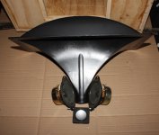
Here's an update. I'm slightly further on from this, in that I've attached the 'mounting plate' for the compression driver...although the silicone is still curing.

The ports are 2.25" from the throat, as it appeared to make the most sense in relation to the Alpha 8's placement - as far from the edge of the cone as was feasible, whilst still hugging the corners.
The ports are 2.25" from the throat, as it appeared to make the most sense in relation to the Alpha 8's placement - as far from the edge of the cone as was feasible, whilst still hugging the corners.
Last edited:
Ports "hugging" the corners on a side wall (where pressure is less) makes a bit more sense, but at least you are in the ballpark now, other than the tuning will be different when you use thicker horn wall panels.The ports are 2.25" from the throat, as it appeared to make the most sense in relation to the Alpha 8's placement - as far from the edge of the cone as was feasible, whilst still hugging the corners.
Are you planning to use bass reflex ports, or just EQ up the falling LF response?
Agreed. I've been accounting for the 1/2" thick MDF that I can use for this horn.
I'd not really re-visited the idea, but I think it would make sense to use reflex ports, especially with only using one mid driver. Maybe I could put the reflex ports on the opposite face for construction's sake. I know in HornResp, the ideal volume for the back chamber of the Alpha 8 is 16 litres, so my next challenge is making an enclosure for the horn that fits.
I suppose I can roughly work this out by using the volume of the horn calculated in the program, and then making a box of 16 litres plus the volume of the horn and the drivers.
To start that's 16+14.909 = 30.909 litres in this case.
I did wire it up this morning, and played a few pieces of music through it. Holy mid-range batman! 🙂 I did have a basic setup with something in place of the Alpha 8 speakers, and I had to EQ up a lot of the upper mid-range.
The Eminence speakers are so sensitive I'm definitely going to have to take that back down again 😉
- Status
- Not open for further replies.
- Home
- Loudspeakers
- Multi-Way
- Midbass horn