thanks Mr.mile,using 2n3055 RCA old stock with Vcc 40Vac and 5Ampere like ax14 sound
AX6 sound like AX14?
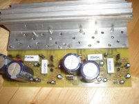
my AX6
nice work.You could replace your 2 x 47pF ceramic capacitors with something better like silver mica or multilayer.
Can BD249C be used as output transistors?
Last edited:
nice work.You could replace your 2 x 47pF ceramic capacitors with something better like silver mica or multilayer.
Can BD249C be used as output transistors?
BD249C and many other transistors can be used as outputs.
is this amply same as bellow
Hi apexaudio your AX6 quit similar to following please give feedback
Motional feed back amplifier - Electronic Circuits and Diagram-Electronics Projects and Design
AX6 sound like AX14?
Hi apexaudio your AX6 quit similar to following please give feedback
Motional feed back amplifier - Electronic Circuits and Diagram-Electronics Projects and Design
Hi, what's the output power with 50Vcc power supply?...I'm building a similar amplifier, with sigle power supply....thanks
Hi, what's the output power with 50Vcc power supply?...I'm building a similar amplifier, with sigle power supply....thanks
35W/4R
Help on AMP
Hello Wiljj78
Can I used 2n3055 instead 2n3773 and bd 139 instead MJE340 any other changes in circuit have to make to work with following supply. I have 22 0 22 AC 1.2A transformer. can it works and how many watts in 8ohm load with this supply.
Ok here's the corrected one....
Regards,
Hello Wiljj78
Can I used 2n3055 instead 2n3773 and bd 139 instead MJE340 any other changes in circuit have to make to work with following supply. I have 22 0 22 AC 1.2A transformer. can it works and how many watts in 8ohm load with this supply.
Attachments
22-0-22Vac gets you to a supply voltage that will allow approximately 28Vpk to 30Vpk into your speaker.
That determines the maximum output power, if you allow sufficient current to flow to the load.
That determines the maximum output power, if you allow sufficient current to flow to the load.
1.2A is a pretty small transformer - It will probably drop from +/-30V all the way to +/-22V under load (about 25 watts RMS). That will make it a bit safer to use 3055's.
When a transformer is loaded that heavily, the leakage reactance will drop the DC down from the peak voltage to the average, which is close to the RMS. And that's even before considering resistive losses. Many a cheap stereo was built this way - especially from the era from where this circuit came.
When a transformer is loaded that heavily, the leakage reactance will drop the DC down from the peak voltage to the average, which is close to the RMS. And that's even before considering resistive losses. Many a cheap stereo was built this way - especially from the era from where this circuit came.
This regulated psu can be use for AX6.
Is the 0.22R resistor for filtering together with the output cap or is it needed for stability?
Is the 0.22R resistor for filtering together with the output cap or is it needed for stability?
You can use this circuit (regulated psu for AX6 ) without 0.22R
Thank you 🙂You can use this circuit (regulated psu for AX6 ) without 0.22R
Another thing I am wondering about. There is a 220R decoupled by 100uF in the voltage gain transistor emitter.
The resistor value is somewhat higher than normal, but decoupled. So, it must be there for DC stability reasons? But is that a big issue with AC coupled load?
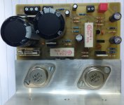
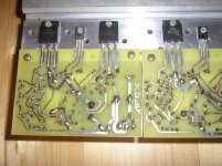
Very nice little amplifier 🙂.
Built and work. Nice warm sound.
regards Olaf
Nice work,
Regards
Very nice little amplifier 🙂.
Built and work. Nice warm sound.
regards Olaf
Sir, can you upload the pdf files for toner transfer.
Thank you..
Regards,
Sir, can you upload the pdf files for toner transfer.
Thank you..
Regards,
ok, I'm going to do tonight
regards Olaf
ok, I'm going to do tonight
regards Olaf
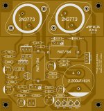
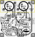
Hi, here are the files. Sorry, I made this layout only to print. The components are not named. Basic for the layout comes from Willy B. Cerna from post #79. Please look at the pictures there and check the component values and the polarity of the capacitors. May be you will find the better layout there 🙂.
regards Olaf
Attachments
Hi, here are the files. Sorry, I made this layout only to print. The components are not named. Basic for the layout comes from Willy B. Cerna from post #79. Please look at the pictures there and check the component values and the polarity of the capacitors. May be you will find the better layout there 🙂.
regards Olaf
Thank you sir...
Regards,
- Home
- Amplifiers
- Solid State
- Retro Amp 50W Single Supply