That was just a theory I threw out there. Honestly, I don't remember the last time I read that paper or if I ever read it at all. Maybe I should have tried to find out before opening my mouth? 😀
I read it more than 10 years ago so I ve forgoten all the facts therein. Im almost certain Oliver didnt make provision for intrinsic emitter resistance but Ill get a copy of the paper again and recheck sometime. We exclusively use sanken BJTs and their sweetspot is far from the 26mv rule, this is biasing for lowest THD.
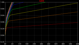
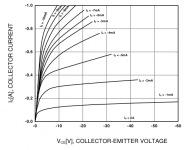
Our company have models made by a specialist third party company that curve trace every batch we ask. This is a costly venture and there are contractural and copyright factors involved for me to post these models. I tested a couple of Bob Cordells models and they are quite accurate according to the datasheet although when actual parts are purchased then there will be variances. Again early voltage problem is observed.
I read it more than 10 years ago so I ve forgoten all the facts therein. Im almost certain Oliver didnt make provision for intrinsic emitter resistance but Ill get a copy of the paper again and recheck sometime. We exclusively use sanken BJTs and their sweetspot is far from the 26mv rule, this is biasing for lowest THD.
Our company have models made by a specialist third party company that curve trace every batch we ask. This is a costly venture and there are contractural and copyright factors involved for me to post these models. I tested a couple of Bob Cordells models and they are quite accurate according to the datasheet although when actual parts are purchased then there will be variances. Again early voltage problem is observed.
Hi Manso,
Are you finding that the optimum bias is greater or less than 26mV across each RE. What value of RE are you using?
The 26mV theory does indeed not take into account the intrinsic ohmic resistance of the emitter, so that resistance will want to subtract from the external value of RE, leaving less than 26mV across the external RE. ALSO, it does not take account of the gate stopper resistance divided by beta of the transistor, nor the compliance of the drivers all the way back to the bias spreader. This stuff can indeed add up. It leads to especially big errors in the 26mV rule if the external RE are small (which can also lead to thermal instability). I don't go below 0.22 ohm RE, and don't go above 5 ohm base stoppers.
Finally, keep in mind that it is better to have the bias err on the high side (gm doubling) than on the low side (class B notch distortion) as long as there is enough thermal stability and heat sinking to keep temperatures safe when the amp errs its bias on the high side.
Early voltage effects in emitter follower output transistors are a much bigger problem in double output stages as opposed to Triples.
Cheers,
Bob
On DIYA's amp , I suggest 30-35mV (across both Re's) as the "rule". Real sound and simulation back this up.
Most use the common NJWxxxx or MJLxxxx ...
If they were to use MT100 Sanken's , the "rule" changes. Both my Japanese
EF3 OPS's (below 1-2) are the sansui -
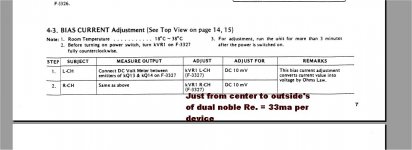
2sc2581/2sa1106 = 10mv/.33Re = <30ma bias per device
Real low - but it sounds/works well ....ps - they say set 10mv between emitters ... 15ma ? whoa.
And the HK -
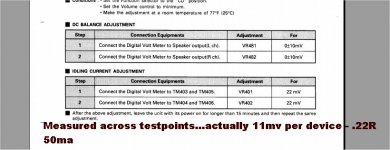
2sc3907/2sa1516 = 22mv halved (TP's across both Re's) 11mv/.22Re = 50ma
Same with the MT200 sanken's , most recommend 35-50ma bias.
MJL21193/4 , I run these "hotter" , a full 40+mv/2X.22Re on my sub.
So , it would seem the manufacturing process determines the "rule" for
optimum bias.
I have not had the pleasure of a semilab MGxxxx series BJT personally , but
elektor's "Q-watt" amp kit suggests a full 44mv/2 X.22Re (100ma) per device.
PS - the MGxxxx's could be "double die" ??
OS
Most use the common NJWxxxx or MJLxxxx ...
If they were to use MT100 Sanken's , the "rule" changes. Both my Japanese
EF3 OPS's (below 1-2) are the sansui -
2sc2581/2sa1106 = 10mv/.33Re = <30ma bias per device
Real low - but it sounds/works well ....ps - they say set 10mv between emitters ... 15ma ? whoa.
And the HK -
2sc3907/2sa1516 = 22mv halved (TP's across both Re's) 11mv/.22Re = 50ma
Same with the MT200 sanken's , most recommend 35-50ma bias.
MJL21193/4 , I run these "hotter" , a full 40+mv/2X.22Re on my sub.
So , it would seem the manufacturing process determines the "rule" for
optimum bias.
I have not had the pleasure of a semilab MGxxxx series BJT personally , but
elektor's "Q-watt" amp kit suggests a full 44mv/2 X.22Re (100ma) per device.
PS - the MGxxxx's could be "double die" ??
OS
Attachments
Last edited:
I don't .. 😀
The different outputs above are ...
either planar , epitaxial , or perforated emitter.
The huge descrepancy between the older sansui sankens
and the newer HK toshiba's recommended bias would have to be that they
are physically different.
One is planar , the other epitaxial.
I'm sure either manufacturer would not mislead us into
improperly setting bias (warranty - sales). 🙂
To say "one size fits all" is incorrect in this case.
PS - the semilabs and the 21193/4's - both perforated emitter ... looks like a trend
(OEM recommendations vs. die technology).
OS
Last edited:
If speed is as important, I'd suggest to use smaller degeneration resistors so that bias can be pushed higher. You guys will have to tell me how small the resistors can be while still having good thermal stability.
THE "trend"
Planar -some MT100 sanken's (older tech)
These can be biased real low. Allows for small heatsink's/ cheap amps.
15-30ma bias
Epitaxial - All the toshiba ON semi "clones" 0281/4281 0302/4302.
here the "rule" is true (60-75ma)
Perforated emitter - all the kits/OEM (and personal experience) ,
A higher "sweet spot" for bias (80ma +)
Semilab OP kits (not many use these OP's)- 100ma.
These are just the approximate guideline's I see between device and
end product.
OS
If speed is as important, I'd suggest to use smaller degeneration resistors so that bias can be pushed higher. You guys will have to tell me how small the resistors can be while still having good thermal stability.
Multiple OP pairs that are well matched and a really "fine tuned" Vbe are
important. OEM OPS's with .1Re almost always specify matching (or to order
the OP's prematched from THEM for $$$ 😀 ).
OS
I was thinking that while base stoppers sort of behave like output degeneration, they also don't help thermal stability because Hfe increases with temperature. So you can probably increase thermal stability if you use L//R or bead//R or just beads as base stoppers. I think this approach would allow us to lower emitter resistors a bit, and base-stopper distortions.
Also, differential thermal runaway (I think that's what it is), where one transistor starts hogging current, is directly related to differential thermal resistance. So if you have a bunch of outputs clamped directly to a copper heat spreader without insulation, there will be very little differential thermal resistance, and minimum risk of runaway current hogging. Or you could just use the Keratherm insulators DIYAudio is selling, as a second-best option.
I think these two methods combined would allow us to use smaller emitter resistors without needing matching. I could do some thermal simulations to find out how much better it would be.
I was thinking that while base stoppers sort of behave like output degeneration, they also don't help thermal stability because Hfe increases with temperature. So you can probably increase thermal stability if you use L//R or bead//R or just beads as base stoppers. I think this approach would allow us to lower emitter resistors a bit, and base-stopper distortions.
That is exactly what the HK990 does.. (bead//R) with .1Re. All else is
pretty much the same as my standard EF3 (the "slew").
Also, differential thermal runaway (I think that's what it is), where one transistor starts hogging current, is directly related to differential thermal resistance. So if you have a bunch of outputs clamped directly to a copper heat spreader without insulation, there will be very little differential thermal resistance, and minimum risk of runaway current hogging. Or you could just use the Keratherm insulators DIYAudio is selling, as a second-best option.
I was a dummy ... and did this with devices on separate heatsinks. Internal Re on a couple of devices "hogged" the current ,
making that heatsink much hotter ... I learned.
OS
Last edited:
Our company have models made by a specialist third party company that curve trace every batch we ask. This is a costly venture and there are contractural and copyright factors involved for me to post these models. I tested a couple of Bob Cordells models and they are quite accurate according to the datasheet although when actual parts are purchased then there will be variances. Again early voltage problem is observed.
Thanks for the explanation.
Here is a page on quasi-sat modeling:
Using the BJT Quasi-Saturation Model
There are a few models in my lib that have the GAMMA and Qco parameters. The KSA1220A/C2690A models have them, and the 1220A model shows a curved Early voltage. The THAT BJT models have these parameters as well. They don't look anything like the datasheet curves though.
Attachments
I was thinking that while base stoppers sort of behave like output degeneration, they also don't help thermal stability because Hfe increases with temperature. So you can probably increase thermal stability if you use L//R or bead//R or just beads as base stoppers. I think this approach would allow us to lower emitter resistors a bit, and base-stopper distortions.
Also, differential thermal runaway (I think that's what it is), where one transistor starts hogging current, is directly related to differential thermal resistance. So if you have a bunch of outputs clamped directly to a copper heat spreader without insulation, there will be very little differential thermal resistance, and minimum risk of runaway current hogging. Or you could just use the Keratherm insulators DIYAudio is selling, as a second-best option.
I think these two methods combined would allow us to use smaller emitter resistors without needing matching. I could do some thermal simulations to find out how much better it would be.
I agree, the size of base stopper resistors can be a concern.
I believe that with proper design, very low distortion can be achieved with 0.22 RE. In some cases I think people are fooling themselves in thinking that overall-real-world performance will be improved by going to 0.15 or even 0.1. Under dynamic conditions with program material changing instantaneous dissipation, bias will of ten move around MORE with such small emitter resistors.
Cheers,
Bob
Let me elaborate: I have found that it is possible to operate power amps with as little as 0.05 ohms successfully, however this is for a single pair of complementary devices. When you SHARE current with multiple devices, then a second problem appears, this is thermal 'hogging' by some devices, leading to thermal runaway.
The formula for optimum transition from Class A to Class B is still valid, but it is difficult to have more than a certain amount of standing current for each device without a somewhat larger Re in each device. This smooths out the differences between different parts of the heat sink characteristics and uneven beta (which can be removed by close matching). The JC-1 power amp DID have some problems with 0.1 ohm resistors, however with 0.15 ohm resistors, and close beta matching, we have been able to make many hundreds of this design without any further problem. IF we were forced to use 0.22 ohms, then we would be forced to use about 0.1A per transistor and this would reduce the Class A standing current to below our design goal of 25W into 8 ohms.
To increase this current further would cause a 'bump' in the transfer function that would be less than optimum.
Bob Cordell (4455)
I believe that with proper design, very low distortion can be achieved with 0.22 RE. In some cases I think people are fooling themselves in thinking that overall-real-world performance will be improved by going to 0.15 or even 0.1. Under dynamic conditions with program material changing instantaneous dissipation, bias will of ten move around MORE with such small emitter resistors.
john curl (4457)
Let me elaborate: I have found that it is possible to operate power amps with as little as 0.05 ohms successfully
John curl! Totally agree with you. The smaller of these resistors, the lower the switching distortion. With Lateral type transistors can opt out of these resistors.
Best regards
Petr
I use 0.22 ohms and run my outputs rich - so well above the 'Oliver' guideline. For example the nx- Amp uses 0.22 Ohms and each pair is biased at 125mA. Nothing stopping me biasing it up even higher either. The sx-Amp is 15 W pure class A, and does about 25 W class AB. Each OP pair runs at 700 mA.
Both these amps sound very smooth - and especially the sx-Amp.
If you are chasing 0 ppm then maybe RE and Iq are critical, but my listening experience tells me these things are not actually the important things wrt sound. Distortion need's to be low, but no need for vanishingly low, and it must be low order (everyone seems to agree with that).
I'm 100 % in Nelson's camp on this.
I have to agree with Bob that the thermal stability issues get very tough with low RE. I think a lot of amps use single slope temp comp and because of the music dynamics, probably have distortion profiles that change with OP device temperature. Although the switching distortion may be higher with higher values of RE (in amps biased for minimum distortion), I believe the profile spread with temp is flatter.
Last edited:
Hi Manso,
Are you finding that the optimum bias is greater or less than 26mV across each RE. What value of RE are you using?
The 26mV theory does indeed not take into account the intrinsic ohmic resistance of the emitter, so that resistance will want to subtract from the external value of RE, leaving less than 26mV across the external RE. ALSO, it does not take account of the gate stopper resistance divided by beta of the transistor, nor the compliance of the drivers all the way back to the bias spreader. This stuff can indeed add up. It leads to especially big errors in the 26mV rule if the external RE are small (which can also lead to thermal instability). I don't go below 0.22 ohm RE, and don't go above 5 ohm base stoppers.
Finally, keep in mind that it is better to have the bias err on the high side (gm doubling) than on the low side (class B notch distortion) as long as there is enough thermal stability and heat sinking to keep temperatures safe when the amp errs its bias on the high side.
Early voltage effects in emitter follower output transistors are a much bigger problem in double output stages as opposed to Triples.
Cheers,
Bob
Hi Bob
I find it to be lower, around 14 to 17mv using Sanken 2sa2223A/2sc6145A which is sanken latest tec audio BJTs. Gate resistors used are 3.9ohm, REs of 0.15ohm and matched of BJT. We use a single super beta (above 1500 Hfe) transistor for VBE for faster temp tracking and lower impedance.
Hi Bob
I find it to be lower, around 14 to 17mv using Sanken 2sa2223A/2sc6145A which is sanken latest tec audio BJTs. Gate resistors used are 3.9ohm, REs of 0.15ohm and matched of BJT. We use a single super beta (above 1500 Hfe) transistor for VBE for faster temp tracking and lower impedance.
For the Sanken pair, could you show the output stage gain ( <1 )vs. the bias current, or is this a trade secret? Assuming this is indeed the optimum for the Sanken pair, what makes you think your finding (14...17mV across .15ohm emitter resistor) is generally optimal?
If it's not, and it's particular to the Sanken pair, why mentioning this out of the proper context? As you see, everybody else prefers biasing the OPS into the gm doubling region, rather than current starving the output stage, and facing higher switching distortions.
- Home
- Amplifiers
- Solid State
- CFA Topology Audio Amplifiers