Thanks for that.
Any ideas on why it oscillated? Comp of the class A control Amp?
The nice thing about these techniques is you don't need to accurately match halves - that's a real benefit for MOSFET output stages.
It oscillated because of too much gain in the OPS differential/CM (local
error correction NFB was to high).
I corrected this with 470R Re ....
With everything corrected - this thing "Rocks" !!
Look at the "monster class A thread" .... I really refined it in the last
few hours.
PS - the FET's really oscillate high (10mhz+) I have not seen that with BJT's !!!
OS
.....no link... as you can see from the example (LF351), it is a very old idea; One of the benefits of collecting circuits for a long time. I believe you can find it on the Internet... it was in a circuits idea collection. I used the idea a few years ago in a Power Amp front end with a better IC OPA, of course, with excellent results. Works very well and cuts costs and size.... a long time favorite area of interest for me... thus, the reason I saved it.
THx- Having fun.
RNMarsh
Amplifier Circuits - Rudolf F. Graf - Google Books
Dan.
I built the amp fig. 1-26 page 19 long time ago and it oscillated without Miller caps as shown in the schematic, but I used different transistors.
ostripper (4394)
When I first reverse engineered it , it was one of 4 paralleled amps.
Forgot to switch it for stand alone operation.
(below) , I scaled it to a 2 pair IRFP 4R/200W class A.
..... still a nice .003% THD20 -4R.
CS's needed more (I) for stability.
edit- broke out into oscillation as soon as it left class A !
ostripper, this scheme unworkable.
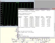
Quiescent current of the output transistors 3.3A (250W)
60V, 1kHz, THD = 0,4%
30V, 20kHz, THD> 5%
at a voltage above 30 V and 20 kHz scheme does not work
Best regards
Petr
When I first reverse engineered it , it was one of 4 paralleled amps.
Forgot to switch it for stand alone operation.
(below) , I scaled it to a 2 pair IRFP 4R/200W class A.
..... still a nice .003% THD20 -4R.
CS's needed more (I) for stability.
edit- broke out into oscillation as soon as it left class A !
ostripper, this scheme unworkable.
Quiescent current of the output transistors 3.3A (250W)
60V, 1kHz, THD = 0,4%
30V, 20kHz, THD> 5%
at a voltage above 30 V and 20 kHz scheme does not work
Best regards
Petr
ostripper (4394)
When I first reverse engineered it , it was one of 4 paralleled amps.
Forgot to switch it for stand alone operation.
(below) , I scaled it to a 2 pair IRFP 4R/200W class A.
..... still a nice .003% THD20 -4R.
CS's needed more (I) for stability.
edit- broke out into oscillation as soon as it left class A !
ostripper, this scheme unworkable.
Quiescent current of the output transistors 3.3A (250W)
60V, 1kHz, THD = 0,4%
30V, 20kHz, THD> 5%
at a voltage above 30 V and 20 kHz scheme does not work
Best regards
Petr
It is a working amp ... had it before me. IRFP's DID dissapate anywhere between 2A and 4A depending on the remotes setting. neither amp blew
after 20 years. heat killed the capacitors
both amps worked after recap.
OPS was both at 75V rails and 4A per device , and I cranked it to house shaking
levels.
PS - It does triangulate at 40K/high amplitude. More work is needed.
30k nearly full power/4R is below .. no 5% ??
OS
Attachments
I built the amp fig. 1-26 page 19 long time ago and it oscillated without Miller caps as shown in the schematic, but I used different transistors.
Of course... you need to put in such details, as required. Did you make a power amp using the concept... IC front end as shown? Nice combo of benefits.
Thx-RNMarsh
Last edited:
Of course... you need to put in such details, as required. Did you make a power amp using the concept... IC front end as shown? Nice combo of benefits.
Thx-RNMarsh
No I did not as I don't have that book, I have a booklet where was that amp from fig. 1-26.
BR Damir
Hello folks,
Can someone please recommend the stable version of this schematic, I have navigated all along this thread but there is so much information that is so difficult to filter. I really appreciate if can point to a schematic or maybe few ? I'm eager to try this wonderful amplifier.
Thanks a bunch.
Can someone please recommend the stable version of this schematic, I have navigated all along this thread but there is so much information that is so difficult to filter. I really appreciate if can point to a schematic or maybe few ? I'm eager to try this wonderful amplifier.
Thanks a bunch.
Hello folks,
Can someone please recommend the stable version of this schematic, I have navigated all along this thread but there is so much information that is so difficult to filter. I really appreciate if can point to a schematic or maybe few ? I'm eager to try this wonderful amplifier.
Thanks a bunch.
That is because it doesn't exist here (yet?)
Thx-RNMarsh
Pioneer CFA
Pioneer C-Z1 circuit, very similar to M-Z1.
http://www.cieri.net/Documenti/Schemi/Pioneer C-Z1 - Circuito SuperLinear.pdf
or you can google Pioneer A-09 service manual.
Regards, Kovax
Jay
If is possible it will be interesting to see M-Z1 detailed input circuit for sure ! ,
------------------------------------------------------------------------
but if someone have schematic of Pioneer H-Z1 headphone Amp. that will be nice to see too ! , since H-Z1 come from same M-Z & C-Z line of products I guess that follow same Non GNFB circuit architecture .
Best Regards !
Pioneer C-Z1 circuit, very similar to M-Z1.
http://www.cieri.net/Documenti/Schemi/Pioneer C-Z1 - Circuito SuperLinear.pdf
or you can google Pioneer A-09 service manual.
Regards, Kovax
ostripper (4405)
It is a working amp ... had it before me. IRFP's DID dissapate anywhere between 2A and 4A depending on the remotes setting. neither amp blew
I got very different results of the simulation
http://s019.radikal.ru/i622/1402/27/1be25c526daa.png
best regards
Petr
It is a working amp ... had it before me. IRFP's DID dissapate anywhere between 2A and 4A depending on the remotes setting. neither amp blew
I got very different results of the simulation
http://s019.radikal.ru/i622/1402/27/1be25c526daa.png
best regards
Petr
I noticed the Marantz MM7025 (a CFA) uses the RET types in the OPS -- 2SC2922/2SA1216. Measured THD in the .005% range at low power levels and increases steadily as the power level increases. Maintanance manual ordered.
Thx-RNmarsh
Thx-RNmarsh
Last edited:
I noticed the Marantz MM7025 (a CFA) uses the RET types in the OPS -- 2SC2922/2SA1216. Measured THD in the .005% range at low power levels and increases steadily as the power level increases.
Thx-RNmarsh
schematic topology uses OPA IC front end buffer. 3EF OPS. Mirror.
View attachment MM7025 schematic.pdf
Got any easy changes to circuit to drop thd at 10KHz? [I've only increased the idle in OPS from 15 to 26Ma]
Thx-RNMarsh
Last edited:
schematic topology uses OPA IC front end buffer. 3EF OPS. Mirror.
View attachment 398414
Got any easy changes to circuit to drop thd at 10KHz? [I've only increased the idle in OPS from 15 to 26Ma]
Thx-RNMarsh
IF You want better performance, go to PM11, or even SM11. I get 0.003%@20kHz 100W 8ohm, with something like SM11, but without the complicated balanced frontend. (OK it still use about 56 transistors/channel)
Sajti
There are many other choices. However, is there something simple to improve This amp's circuit? I got it relatively cheap (open box sale). Sounds surprisingly good, though. Something to play with for awhile.
[It does not have enough power and neither would the SM11/PM11]
Thx-RNMarsh
There are some steps to get better performance, but it will increase the complexity of the circuit. I'm not a big fan of the opamps. So this would be the 1st I would remove.
You can increase the output power to use stronger PSU, and more output devices. The original PM11S1 runs with +/-65V, and if You can keep this voltage You can get 170-180W/8ohms. You need at least 3 pairs 2922/1216 for this power.
Sajti
You can increase the output power to use stronger PSU, and more output devices. The original PM11S1 runs with +/-65V, and if You can keep this voltage You can get 170-180W/8ohms. You need at least 3 pairs 2922/1216 for this power.
Sajti
One more idea:
Just check the Marantz way:
The MM7025 circuit is almost same as PM7001 (output devices are better),
the next step is PM8004, with more complex power amp section, than comes the PM11, with the famous separated voltage gain stage, and finally the SM11S1 with balanced input. This can be the way to increase the quality.
Sajti
How to make a good separate CFA voltage gain stage, would that not belike a higher voltage headphone amp..??
schematic topology uses OPA IC front end buffer. 3EF OPS. Mirror.
View attachment 398414
Got any easy changes to circuit to drop thd at 10KHz? [I've only increased the idle in OPS from 15 to 26Ma]
Thx-RNMarsh
It should be pretty simple, change compensation and obtain two pole response, THD will probably be halved, all that will be needed is two extra caps and 2 extra resistors, maybe 4 resistors for better gain margins. See the example I posted a while back. Post 1545 in this thread.
Idle at 26ma is far from ideal, around 70 ma is more in the ball park.
Last edited:
- Home
- Amplifiers
- Solid State
- CFA Topology Audio Amplifiers