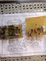
Driver Stage Tested
warm regards
andrew
Excellent ... The board MOD BX was very well put together ...
You will love this amp is very strong!
What about the current capability of the amp and the SOAR? Please be aware that if you specify an amp for 2 Ohms, real-world load might incidentally be in the range of 0.5 Ohms... At 2 Ohms (resistive) you'll need 22.5 Amps. To be stable with 2 Oms loudspeakers, the stage hast to be able to deliver 90 Amps...Debunker is 500W 2R with TDH 0.02 % and the plate for a low price .
I guess it turns out to be a 125 Watts in 8 Ohms amp 😀
Friend to the 70V symmetrical pattern that Renato did gave a consumption of 5A Voltage ie 10A total current. by the simulation program and practices rendimendo was otimo
What about the current capability of the amp and the SOAR? Please be aware that if you specify an amp for 2 Ohms, real-world load might incidentally be in the range of 0.5 Ohms... At 2 Ohms (resistive) you'll need 22.5 Amps. To be stable with 2 Oms loudspeakers, the stage hast to be able to deliver 90 Amps...
I guess it turns out to be a 125 Watts in 8 Ohms amp 😀
Good day ...
I posted file for simulation, I posted the link to download the demo version of NI Multisim 30 days in functionality, I posted pictures of the simulation for those who do not want to install Multisim, but even so, questions persist.
Yes friend, your calculations are correct, the amp delivers 500W at 2 ohms, actually. 500W is the power it will deliver you with an excellent THD and LIMIT work of the power transistors (MJLs), endowed with a generous sink.
If you use larger than 2 ohms impedance on the outputs, it is logical that the power will be reduced, as well as the heating of the output transistors. But is this clearer than the sun, I figured it would not be necessary to explain ...
Even so, I decided to make a new simulation, but this time, I'm DRAWING on it, so that in this way there is no longer any doubt:
An externally hosted image should be here but it was not working when we last tested it.
Save your calculations, Multisim does it for you and let you go wrong.
If it becomes further questions, do not try to convince anyone else. Who want to ride, you can see that the amplifier is able, indeed. Who does not want to ride, just choose one of the other numerous projects posted here in this great forum, simple as that.
Regards
Last edited:
An externally hosted image should be here but it was not working when we last tested it.
In summary, if you mount a stereo (two PCBs) and operate the unit 2 ohms each side, you will have a Hifi amplifier of 1000WRMS. There is good?
Last edited:
But multisim does not take the SOA of your power transistors into account.
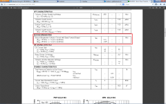
The datasheet I have for MJL21194 does not have a DC SOA curve but a 1Sec SOA Curve.
From that graph, IMO 4 pairs of MJL21194 at 65-70V per rail, won't power a 2R load with any reliability.
But then again I guess it would most prob only be used at 250W max in reality
The datasheet I have for MJL21194 does not have a DC SOA curve but a 1Sec SOA Curve.
From that graph, IMO 4 pairs of MJL21194 at 65-70V per rail, won't power a 2R load with any reliability.
But then again I guess it would most prob only be used at 250W max in reality
Last edited:
But multisim does not take the SOA of your power transistors into account.
The datasheet I have for MJL21194 does not have a DC SOA curve but a 1Sec SOA Curve.
From that graph, IMO 4 pairs of MJL21194 at 65-70V per rail, won't power a 2R load with any reliability.
But then again I guess it would most prob only be used at 250W max in reality
An externally hosted image should be here but it was not working when we last tested it.
Do not know which data sheet you have on hand, however, follows up.
And honestly, I suggest you not mount this amplifier. There are many "good projects" here on the forum with "great theory" in calculations, certainly much higher than this.
This design fo posted for those who admire quality sound. Was posted for those who like to assemble and demonstrate the results, and not to be discussed without foundation.
Unlike many posted, has simulation, has video, prints have ... But I repeat: Who disagrees that just will not mount. IGNORE THE TOPIC.
There's a fine line between theory and practice, and between the two, always stayed with practice. The project was tested physically, you do not trust the information posted here, I repeat: IGNORE THE TOPIC.
Ok ill take your advice and ignore this thread.
Was just trying to help,
But you don't have to accept that you reading the datasheet wrong, and obviously have no intention to take advice.
Was just trying to help,
But you don't have to accept that you reading the datasheet wrong, and obviously have no intention to take advice.
But multisim does not take the SOA of your power transistors into account.
The datasheet I have for MJL21194 does not have a DC SOA curve but a 1Sec SOA Curve.
From that graph, IMO 4 pairs of MJL21194 at 65-70V per rail, won't power a 2R load with any reliability.
But then again I guess it would most prob only be used at 250W max in reality
Look to the OEM's. ALL use either low rail (40-50V) EF3 (3-4 pair for BJT)
or just use Class D for 2R reliable operation.
This applies universally for both home audio plate amps AND car audio.
An EF2 , at lower rails ... would come close to SOA and "droop" even
with 4R.
OEM's mostly don't even bother with AB for 2R - class D only.
PS -A 2R driver can have a much lower Z above and below resonance.
OS
Renat ... those specs you highlighted are at very low voltage. At 60V+
rails these devices can barely do 2A each (that is the purpose for SOA
graph in datasheet) !!
One of these OP devices used as a 12V regulated power supply could
do 15A .... that is what this spec really means.
OS
rails these devices can barely do 2A each (that is the purpose for SOA
graph in datasheet) !!
One of these OP devices used as a 12V regulated power supply could
do 15A .... that is what this spec really means.
OS
Last edited:
Ok friends ...
Again, I will not discuss theory ...
Once you can put a video here, with tests of scope ok with phantom load.
Vostro, know that your intention is to help, do not want to be rude. If you think you can judge with calculations that the maximum power it can deliver to you in 2 ohms is 250W, I respect your opinion, but practice proves otherwise. Physical tests, provided with adequate support power dissipation in which I labeled on the PCB with 70-70V.
We tested things differently around here so ... Applied in practice and observe to what extent support ...
Regards
Hi Friend,Ok friends ...
Again, I will not discuss theory ...
Once you can put a video here, with tests of scope ok with phantom load.
Vostro, know that your intention is to help, do not want to be rude. If you think you can judge with calculations that the maximum power it can deliver to you in 2 ohms is 250W, I respect your opinion, but practice proves otherwise. Physical tests, provided with adequate support power dissipation in which I labeled on the PCB with 70-70V.
We tested things differently around here so ... Applied in practice and observe to what extent support ...
Regards
Sorry to say, but that what you call theory is practice.
Loudspeakers are no pure resistive load. They combine resistive with inductive and capacitive components, as well as a counter EMF. Bottom-line is, that a 2 Ohms loudspeaker, under circumstances, can act like a way lower impedance. Your amplifier must be able to handle that impedance without frying the power-stage.
Since your design also lacks a minimal form of protection, I'd advice not to use it with loads under 8 ohms nominal at the rated rail-voltage.
Regards.
Hi Friend,
Sorry to say, but that what you call theory is practice.
Loudspeakers are no pure resistive load. They combine resistive with inductive and capacitive components, as well as a counter EMF. Bottom-line is, that a 2 Ohms loudspeaker, under circumstances, can act like a way lower impedance. Your amplifier must be able to handle that impedance without frying the power-stage.
Since your design also lacks a minimal form of protection, I'd advice not to use it with loads under 8 ohms nominal at the rated rail-voltage.
Regards.
8 ohms?
😱😱😱😱😱😱
8 ohms I use it yourself in a TDA7294 supports 4 ohms, not an amplifier with 4 output pairs that have physically endured this burden.
Say that an amplifier with 4 pairs only supports 8 ohms is the same as telling a joke.
Seems to me that there are several experts here, too, but far from my humble ability to make, show, demonstrate and prove that it works, video and photo.
I begin to understand why certain charlatans get along here. The folks around here like to chat over what projects to assemble ...
Definitely does not have the dialogue here. This is my last message, I will not waste my time, I will no longer monitor this topic.
Feel free, make the topic they wish, seek errors, defects, feel free ... You are the experts!

I regret your reactions to my remarks, but no sweat... it's your design and your responsibility. I was only trying to help.
Friends I guess you can not judge an amplifier without the proper testing, I believe that in the case of a class AB deserves a test for the market to be saying something so false an amplifier 1000W and the end is pure deception.
This amplifier has been tested by others in different impedances, I am the supplier of pcbs and already sold more than 80 pcbs at first and had no problem in your installation, ask those who criticize forming an assembly before and have a basis for questioning the project.
This amplifier has been tested by others in different impedances, I am the supplier of pcbs and already sold more than 80 pcbs at first and had no problem in your installation, ask those who criticize forming an assembly before and have a basis for questioning the project.
An externally hosted image should be here but it was not working when we last tested it.
Do not know which data sheet you have on hand, however, follows up.
Without comment....
Sajti
Attachments
You are absolutely right that judging something (in this case an amp) without proper testing is not correct. And I really appreciate you defending your friends design!Friends I guess you can not judge an amplifier without the proper testing, I believe that in the case of a class AB deserves a test for the market to be saying something so false an amplifier 1000W and the end is pure deception.
This amplifier has been tested by others in different impedances, I am the supplier of pcbs and already sold more than 80 pcbs at first and had no problem in your installation, ask those who criticize forming an assembly before and have a basis for questioning the project.
Testing being my business, I know review based on paper specs ought to precede actual testing. Imho the amp already failed on that review.
As I earlier calculated, the power-stage does not come close to the minimum current requirements (approx. 23 Amps peak @ +- 70V rail) to support 500W @ 2 Ohms. The 4 transistors only supply a peak of some 10 Amps at that rail-voltage, perhaps a bit more, but not the required 23A. And that is only when a pure resistive 2 Ohms load is connected!
When a real-world load is connected, the game changes completely: the dc resistance of a 2 ohms loudspeaker is likely to be in the range of 1.2 to 1.8 ohms. With reverse EMF it can (under circumstances) be even lower than 1 Ohm. So, that's my basis for questioning the 500W @ 2Ohms claim. At half power the thermal situation of a power-stage is even worse!
If the number of transistors in the output-stage is increased, the situation would be better.
Cheers.
300/500W Subwoofer Power Amplifier
Amplificador de 660 ~ 700 Watts RMS 4 Ohms mono | Toni Eletronica OneToni Eletronica One (verso mobile)
Amplificadores de potencia - parte 5 amplificador expandible
Proyectos electronicos DIY Construya un amplificador estereo de 500w
solidstateamps2bjts
A680 2SA1943 2SC5200 / MJL21193 MJL21194 Power Amplifier Module (Stereo)_Solid-State Amp_Analog Metric - DIY Audio Kit
http://www.diyaudio.com/forums/solid-state/181769-first-stumbling-steps-solid-state-3.html
350w Home audio amplifier - HQEW.net
- Home
- Amplifiers
- Solid State
- Debunker Strong X4 - 500 WRMS Hi-Fi Amp