My mistake, I should have written DCB1.
Hi, would you have a drawing of your implementation of the tl431's?
It would be much appreciated! 🙂
Regards
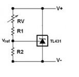
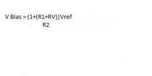
It's a standard shunt regulator configuration with the current limiting resistor removed, same as any bias generator in Papa's amps.
RV=5K
R1= linked out to save space
R2=1K
Vref = 2.495V
RV=5K
R1= linked out to save space
R2=1K
Vref = 2.495V
Attachments
Last edited:
Does the B1 have any LEDs to be replaced?
Or do you mean you modified a DCB1?
The B1 doesn't have its PSU built onto the board, with the exception of the two big 10000uF caps. This means you have the facility to play with PSUs as I did.
It's a standard shunt regulator configuration with the current limiting resistor removed, same as any bias generator in Papa's amps.
RV=5K
R1= linked out to save space
R2=1K
Vref = 2.495V
Much noisier than LEDs though.
Agreed, but in their function they will still be inaudible.
As with everything, it's a compromise, the benefit of using the TL431 over the LEDs is that if there is a slight DC offset on the outputs (in the same direction), it can be nulled by trimming one of the supply rails, rather than risking damage to the PCB by swapping LEDs.
As with everything, it's a compromise, the benefit of using the TL431 over the LEDs is that if there is a slight DC offset on the outputs (in the same direction), it can be nulled by trimming one of the supply rails, rather than risking damage to the PCB by swapping LEDs.
Agreed, but in their function they will still be inaudible.
As with everything, it's a compromise, the benefit of using the TL431 over the LEDs is that if there is a slight DC offset on the outputs (in the same direction), it can be nulled by trimming one of the supply rails, rather than risking damage to the PCB by swapping LEDs.
I wasn't referring to swapping LEDs once soldered. Just measure them under operating condtions on a bread-board.
Thinking of it (+12dB gain, great sounding and neutral in character, using +/-10V PSU, no coupling caps and designed in compliance with B1/Pass concepts) I came to this idea (in attachment) based on Mr. Pass' proposal from BAF2013. Having LSK/LSJ JFETs available makes this possible.
J310 CCS provides about 20mA each, LSK/LSJ JFETs work at Vds of 7.5V and with Id at about 80% of Idss. P1 enables dynamic matching/distortion profile optimizing and P2 sets the DC offset.
Preamp's max. output is about 7V_peak of clean swing.
Zout is determined by value of R9 and it's not critical (R9/R6 ratio determines the gain of the circuit) since we have a Mesmerize buffer stage next to it.
I think they will work great together. AFAIC, it would be very difficult to find a better sounding gain stage...
I really love this Juma!
What Idss do I need for the JFets?
I wanted my DCB1 to be combined with a BA3 as a pre, but maybe this is even better for switching in some extra gain when needed.
And it is DC coupled.
Thanks
I wasn't referring to swapping LEDs once soldered. Just measure them under operating condtions on a bread-board.
Unsoldered the leds on the negative rail and moved them to breadboard.
Free to roll leds now wthout more soldering. I'll put them back when done.
Regards
Unsoldered the leds on the negative rail and moved them to breadboard.
Free to roll leds now wthout more soldering. I'll put them back when done.
Regards
No matter how well matched they won't give same V+/V- if you won't do the Jfet "leg trick" that I linked you, I repeat.
Plus you should measure them as a bunch of five driven by their associated JFET to go in the board under 0.6V VDS in IDSS mode. If you want absolute predictability. It amounts to no performance gain is my 2C. Aesthetics.
I trust you salas, but I probably need to find it out the hard way by myself. 🙂
Btw - the breadboard is in circuit. 🙂
Regards
Btw - the breadboard is in circuit. 🙂
Regards
... What Idss do I need for the JFets?...
About 12mA, but anything from 8 to 15mA will do great.
I believe I managed to kill one of the fets... 🙁
The positive rail jumped from 9.8v to 14.4v.
I will continue to measure tomorrow.
Regards
The positive rail jumped from 9.8v to 14.4v.
I will continue to measure tomorrow.
Regards
Help please 🙂
Well, I measured the voltages and wrote them down in the schema.
Please have a look and advise. My believe is that I blew Q2 - one of the IRFP9240's. 🙁
All leds lights up and the ones on the positive rail glows brighter now...
Regards
Well, I measured the voltages and wrote them down in the schema.
Please have a look and advise. My believe is that I blew Q2 - one of the IRFP9240's. 🙁
All leds lights up and the ones on the positive rail glows brighter now...
Regards
An externally hosted image should be here but it was not working when we last tested it.
Last edited:
- Home
- Amplifiers
- Pass Labs
- Mezmerize DCB1 Building Thread