Hi Christophe
Thank you.
Cheers, E.
Good engineering, Edmond (as habit ;-)
Thank you.
I don't see any reason why it should have an impact on slew rate. As for poles, yes, it will add a pole, though at a very high frequency. Normally, this should not cause serious problems, only some more phase shift at frequencies as high as 10MHz. Besides, in case of using low noise high gain trannies, which have most of the time a relative low max. Vce, you will need cascodes anyway.Any impact on the input stage by the add of the cascode (slew rate, pole etc.)?
Cheers, E.
Scott, we need you to bring your CFA definition, or arbitration.
This has possibly been a little too contentious. I stick with the feedback network being a major portion of the forward transfer function.
Food for thought, I have seen few if any active feedback amplifiers in audio. It is true getting better than -70dBc is real work with them but they fall into a different class alltogether
Constant gain bandwidth is also a property of dominant pole compensation. If you have a system with two poles, you have to use MC, or, some more complicated technique to deal with the excess phase shift.
Last edited:
"A "CFA" is a "VFA" having the open loop gain (and loop gain) controlled/modulated by the feedback network."
Nonsense.
They are different. Period.
Nonsense.
They are different. Period.
I stick with the feedback network being a major portion of the forward transfer function.
"A "CFA" is a "VFA" having the open loop gain (and loop gain) controlled/modulated by the feedback network."
Nonsense.
They are different. Period.
I hope Mr. Wurcer won't take offense on this. It appears to me that his definition is essentially the same as mine.
"feedback network being a major portion of the forward transfer function"
and
"open loop gain (and loop gain) controlled/modulated by the feedback network"
Let me try this on for size, as to VFA and CFA.
Look at where the current in the feedback resistor goes when there is no input signal. In a VFA, virtually all of it goes through the feedback network shunt resistor. In a pure CFA, virtually all of the current in the feedback resistor goes into the low-impedance node of the first stage (e.g., the emitter circuit), and little or none goes through the feedback network shunt resistor.
In both cases where we have a voltage amplifier (voltage in, voltage out) whose gain is set by feedback, the gain is usually set by a voltage divider consisting of the feedback resistor and the feedback network shunt resistor. In both cases the shunt resistor plays a critical role in setting the closed-loop gain. In a VFA, this divided voltage is compared to the input voltage and an error VOLTAGE is amplified by the input stage. In a CFA, the Thevenin equivalent voltage from this network is compared to the input voltage and an error CURRENT results that is passed through the input stage to the input stage load.
So, one can define a CFA/VFA as a matter of degree. If all of the current in the feedback resistor flows through the shunt resistor, it is a VFA. If all of the feedback resistor current flows into the input stage, and none through the shunt resistor, it is a CFA. Bear in mind this is a feedback current that flows when the input to the amplifier is zero. Think of the source as being a signal injected within the amplifier, like noise.
In a real amplifier with a CFA-like topology, the impedance at the input stage feedback node (e.g., the emitter) is never zero, so some of the feedback current flows in the feedback shunt resistor. There is thus a degree to which an amplifier is a CFA. If 70% of the feedback current flows into the input stage, we have an amplifier that is 70% CFA. There is thus a spectrum between CFA and VFA operation.
Consider a CFA with a diamond input stage with each transistor operating at 1.5mA, and with 40 ohms in each emitter. Re' for each input transistor is about 17 ohms. The input impedance of the input stage that is seen is thus about (40+17)/2 = 29 ohms. Lets further say that the feedback shunt resistor is 40 ohms. Then about 69% of the current in the feedback resistor will flow into the low-z input node of the input stage. So, by this reasoning, this amplifier would be a 69% CFA.
Is this a reasonable way to describe the difference between CFA and VFA?
Cheers,
Bob
If we consider the inverting device as part of the feedback path, not the case with a LTP ?I stick with the feedback network being a major portion of the forward transfer function.
I hope Mr. Wurcer won't take offense on this. It appears to me that his definition is essentially the same as mine.
"feedback network being a major portion of the forward transfer function"
and
"open loop gain (and loop gain) controlled/modulated by the feedback network"
It's the 'it's a VFA . . . bit that you inserted that I objected to. '
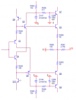
Instead of quibbling about the definition of CFA and VFA amps, let's see how we can improve a CFA input stage. We know already that for lowest distortion RE = 0.5/gm = 0.5 VT / Ic or 13mV / Ic at room temperature (and ignoring bulk resistances for a moment). A weak point of a so called 'CFA' input stage is the not so good PSRR and the susceptibility of noise from the current sources (CCS) which are needed to bias the input stage. The PSRR can be improved by using cascodes, while the impact of CCS noise can be reduced by using a diamond configuration and proper choices of the emitter resistors. As far as I can see, this is only possible if the collectors of the first transistor pair are connected either to the emitters of the second transistor pair (fig.1) or to the feedback node (fig.2). If the collectors are tied the to supply rails, it is not possible to cancel out the CCS noise.
Of course one could calculate analytically the proper values of the emitter resistors, but as I am lazy, I used my simulator to figure it out, though it's an iterative process.
In the example below, Ic of the output trannies (Q3 & Q4) were set to 1mA. So for lowest distortion RE2 should be: 0.5 * VT / Ic = 13 Ohms. Check this as shown in fig.1.
By means of a VCCS G1 an AC current -representing the noise- has been injected (see fig.2). Adjust RE1 (and keep Ic =1mA by also adjusting Ib of the CCSes I1 and I2) for the lowest output signal. With RE1 = 5 Ohms the output signal was about 50dB lower compared to a circuit where the collectors of Q1 and Q2 were tied to the supply rails. If the collectors are connected as shown in fig.1, RE1 should be 7.5 Ohms.
In this simulation perfectly matched trannies were used. So in real life the CCS noise reduction will be less impressive. Also notice that the optimal resistor values should not only be adjusted for the emitter bulk resistance but also depend on VT, being a function of temperature.
Cheers, E.
models:
.MODEL BC550G NPN (IS=1.8E-14 BF=1k NF=1 VAF=1k ISE=5E-14
+ NE=1.46 BR=35.5 NR=1 VAR=1k IKR=.03 ISC=1.72E-13 NC=1.27
+ CJE=13P CJC=4P VJC=.54 MJC=.33 TF=.64N TR=50N)
.MODEL BC560G PNP (IS=1.8E-14 BF=1k NF=1 VAF=1k ISE=5E-14
+ NE=1.46 BR=35.5 NR=1 VAR=1k IKR=.03 ISC=1.72E-13 NC=1.27
+ CJE=13P CJC=4P VJC=.54 MJC=.33 TF=.64N TR=50N)
Even better is attached, provides lower distortions (if anybody cares about) and avoids uselessly loading the cascode with the input stage bias current. You now can run the input diamond buffer as hot as you like (which could be a good idea, for lower voltage noise). Also significantly lowers the diamond buffer power dissipation.
Attachments
Last edited:
It's the 'it's a VFA . . . bit that you inserted that I objected to. '
Well, get used with the truth. The feedback type has nothing to do with any particular circuit topology. Your criteria and pointers were proved partially wrong just a few pages up.
In both cases where we have a voltage amplifier (voltage in, voltage out)
Bingo, Mr. Cordell. The rest is the usual explanation that was provided ad nauseam here.
May I suggest the CFA fans to calculate a percentage for the usual audio implementation? For the common closed loop gains, audio CFAs I've seen here are in fact not more than 5-10% CFA.
Last edited:
As a corallary to what I suggested above, if we decrease the value of the shunt resistor in a VFA, the closed-loop gain will increase by so many dB and the closed loop bandwidth will decrease by a corresponding amount. The loop gain will decrease by so many dB.
In a pure CFA, if we drop the value of the feedback shunt resistor, the closed loop gain will increase by so many dB, but the closed loop bandwith and loop gain will be largely unaffected.
In the early 1970's, we used CFAs to equalize twisted pair telephone lines out to about 1MHz using CFAs. This was at Bell Labs on the Picturephone project. The rising gain needed to equalize the line was achieved by making the feedback shunt network impedance fall with increasing frequency. That network usually consisted of numerous series R-C combinations together in parallel. The advantage of the CFA was that the loop gain did not decrease with increasing closed loop gain.
Cheers,
Bob
Thank you Mr. Cordell for describing the exact differences that differentiates VFA and CFA.
Not to make things too complex, then there's a hope we stick with the main controlling mechanism more than 50% current = CFA and less than 50%= VFA.
Then the discussion is over and we can focus on the qualities of the different circuits.🙂
Not to make things too complex, then there's a hope we stick with the main controlling mechanism more than 50% current = CFA and less than 50%= VFA.
Then the discussion is over and we can focus on the qualities of the different circuits.🙂
Bingo, Mr. Cordell. The rest is the usual explanation that was provided ad nauseam here.
May I suggest the CFA fans to calculate a percentage for the usual audio implementation? For the common closed loop gains, audio CFAs I've seen here are in fact not more than 5-10% CFA.
Again Waly, you apply canonical feedback terminology to incorrectly characterize a CFA as a VFA amplifier. There is no doubt that a CFA can be configured for voltage amplification such that the output controlled quantity is voltage. That does not support the notion that CFA= VFA.
CFA the feedback into the inverting pin is in the form of a current, and VFA ( even summing junction) in the form of a voltage.
Last edited:
Let me try this on for size, as to VFA and CFA.
Look at where the current in the feedback resistor goes when there is no input signal. In a VFA, virtually all of it goes through the feedback network shunt resistor. In a pure CFA, virtually all of the current in the feedback resistor goes into the low-impedance node of the first stage (e.g., the emitter circuit), and little or none goes through the feedback network shunt resistor.
In both cases where we have a voltage amplifier (voltage in, voltage out) whose gain is set by feedback, the gain is usually set by a voltage divider consisting of the feedback resistor and the feedback network shunt resistor. In both cases the shunt resistor plays a critical role in setting the closed-loop gain. In a VFA, this divided voltage is compared to the input voltage and an error VOLTAGE is amplified by the input stage. In a CFA, the Thevenin equivalent voltage from this network is compared to the input voltage and an error CURRENT results that is passed through the input stage to the input stage load.
So, one can define a CFA/VFA as a matter of degree. If all of the current in the feedback resistor flows through the shunt resistor, it is a VFA. If all of the feedback resistor current flows into the input stage, and none through the shunt resistor, it is a CFA. Bear in mind this is a feedback current that flows when the input to the amplifier is zero. Think of the source as being a signal injected within the amplifier, like noise.
In a real amplifier with a CFA-like topology, the impedance at the input stage feedback node (e.g., the emitter) is never zero, so some of the feedback current flows in the feedback shunt resistor. There is thus a degree to which an amplifier is a CFA. If 70% of the feedback current flows into the input stage, we have an amplifier that is 70% CFA. There is thus a spectrum between CFA and VFA operation.
Consider a CFA with a diamond input stage with each transistor operating at 1.5mA, and with 40 ohms in each emitter. Re' for each input transistor is about 17 ohms. The input impedance of the input stage that is seen is thus about (40+17)/2 = 29 ohms. Lets further say that the feedback shunt resistor is 40 ohms. Then about 69% of the current in the feedback resistor will flow into the low-z input node of the input stage. So, by this reasoning, this amplifier would be a 69% CFA.
Is this a reasonable way to describe the difference between CFA and VFA?
Cheers,
Bob
I am going to stick with my two tests and two pointers. Seems to work pretty well for me 🙂
Last edited:
CFA PSR

I'm rather disappointed that even some of yus true gurus, with the notable exception of Guru Stuart, have a secret semantic pedantic side 😱
Guru Cordell, I'm not sure your question helps us design better amps unless we want to improve on Williamson valve stuff.
Why does a CFA have poorer PSRR?
My $0.02 is that its simply due to low Loop Gain caused by the symmetrical topologies that are thought essential. I need to explore Edmond's CMF (hope I got da TLAs right) topologies to see if we can deal with this simply.
Noise from the CCSs can be dealt with by suitable choice of RC decoupling ... as is essential anyway. The simple CFAs I posted earlier in this thread are really LC's VSSA modified to do this and make more effective use of the evil large electrolytics.
Would the true gurus please tell us why CFAs have poorer PSRR?
_________________
Edmond, could you explain a bit more about
What is VT? Is this 'lowest distortion' dodge only for diamond CFA inputs?
_________________
Waly, can you tell us where the circuit you posted in #3149 in reply to Edmond comes from? Is it your own invention? Have you tried it in real life? Got some numbers ... preferably 'real life' but SPICE world will do.
I'm pleased you've applied yourself to helpful stuff ... as opposed to the 'yus guys are all idiots & deaf' diatribes. 🙂
Hear! Hear!Instead of quibbling about the definition of CFA and VFA amps, let's see how we can improve a CFA input stage.
I'm rather disappointed that even some of yus true gurus, with the notable exception of Guru Stuart, have a secret semantic pedantic side 😱
Guru Cordell, I'm not sure your question helps us design better amps unless we want to improve on Williamson valve stuff.
Can we explore this possible myth further. If we understand it, we can probably find several other easy ways to deal with it. May I askWe know already that for lowest distortion RE = 0.5/gm = 0.5 VT / Ic or 13mV / Ic at room temperature (and ignoring bulk resistances for a moment). A weak point of a so called 'CFA' input stage is the not so good PSRR and the susceptibility of noise from the current sources (CCS) which are needed to bias the input stage. The PSRR can be improved by using cascodes, ... loadsa good stuff. ...
Why does a CFA have poorer PSRR?
My $0.02 is that its simply due to low Loop Gain caused by the symmetrical topologies that are thought essential. I need to explore Edmond's CMF (hope I got da TLAs right) topologies to see if we can deal with this simply.
Noise from the CCSs can be dealt with by suitable choice of RC decoupling ... as is essential anyway. The simple CFAs I posted earlier in this thread are really LC's VSSA modified to do this and make more effective use of the evil large electrolytics.
Would the true gurus please tell us why CFAs have poorer PSRR?
_________________
Edmond, could you explain a bit more about
I thought increased RE will always reduce distortion cos it is feedback.lowest distortion RE = 0.5/gm = 0.5 VT / Ic or 13mV / Ic at room temperature
What is VT? Is this 'lowest distortion' dodge only for diamond CFA inputs?
_________________
Waly, can you tell us where the circuit you posted in #3149 in reply to Edmond comes from? Is it your own invention? Have you tried it in real life? Got some numbers ... preferably 'real life' but SPICE world will do.
I'm pleased you've applied yourself to helpful stuff ... as opposed to the 'yus guys are all idiots & deaf' diatribes. 🙂
Last edited:
I am going to stick with my two tests and two pointers. 🙂
No problem, if it fits your agenda 😛.
Again Waly, you apply canonical feedback terminology
Correct.
Is there any widely accepted terminology and methodology beyond the feedback theory? BTW, jcx posted a few pages up a webarchive.org a link to an excellent article about feedback types and methodologies.
Why does a CFA have poorer PSRR?
Elementary, my dear Watson 😀.
In a long tail pair input stage, the power supply perturbations are common mode to the input stage, hence they are rejected by the high CMRR. No such effect in a diamond buffer input stage. That's also why the known Lin topology has an asymmetrical PSRR, the VCC PSRR being much larger.
There is a very interesting article posted by jcx somewhere in this thread, about a general relationship between the PSRR, CMRR and OLG in op amps. As you see, nothing to do with the feedback type, VFA or CFA.
Last edited:
- Home
- Amplifiers
- Solid State
- CFA Topology Audio Amplifiers