OK, I'v settled on 2.7k as the feedback resistors. That brings the gain down a bit and yet keeps the dynamics in balance. But overall, this feedback arrangement is not massively different than the original with the 2 x 1k resistor divider off the OPT secondaries. Maybe a bit of tweaking on them would make more of a change maybe.
Anyway, it does sound very good. One of the better sounding valve amps I'd say. Now it would be interesting to try the other valves. My local guitar shops have some 6L6 for €40 a matched pair. Might be worth trying them out.
Fran
Anyway, it does sound very good. One of the better sounding valve amps I'd say. Now it would be interesting to try the other valves. My local guitar shops have some 6L6 for €40 a matched pair. Might be worth trying them out.
Fran
Good stuff!
I would love to roll some driver tubes in there like KT88 or KT77 and at 89mA per pair I bet the 6L6 would sound great too and not break the bank.
check this out...
http://thetubestore.com/teslakt77.html
I would love to roll some driver tubes in there like KT88 or KT77 and at 89mA per pair I bet the 6L6 would sound great too and not break the bank.
check this out...
http://thetubestore.com/teslakt77.html

OK,
I did rewire the heaters and that reduced the bit of hum I had - there is still a little there on one channel only, and I can't chase it down. I can only hear it when I'm within a foot or 2 of the speaker. Amp sounds wonderful - very happy indeed with it.
Well worth making....
Fran
I did rewire the heaters and that reduced the bit of hum I had - there is still a little there on one channel only, and I can't chase it down. I can only hear it when I'm within a foot or 2 of the speaker. Amp sounds wonderful - very happy indeed with it.
Well worth making....
Fran
did you lift the heaters with dc? you can use the 34volts dc bias at the cathodes of the el34's for that....
The 6SN7 heaters are floated pretty much exactly as per the schematic, except I used a spare twisted pear DC supply for the 6SN7s and AC with a humbucker for the EL34s. The rewiring I did though was to lay a separate run of heater wiring to each EL34 heater. I read it was recommended somewhere (lost the reference). Apparently daisy chaing one heater on to the next is not a great idea and running a separate run to each valve reduces the scope for hum. I had noticed that the buzz/hum I was hearing got a little worse as the amp heated up over an hour or so. It helped in this case at least, maybe it wouldn't make a difference elsewhere.
Its a little strange that the slight buzzy hum I'm left with is in one channel only and at this point I can only think that its down to physical placement of transformers or something. The reality is that while the challenge of making is quieter is attractive, the level is so low as to not be audible and it doesn't bother me. At some point I'll try chasing it down a little more....
Fran
Hey All,
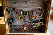
The IXCP10M45S current regulator in the EL34 music machine shown in #20 in this thread. Can it be lifted and used with 6CG7's in a phase splitter? And if it acts as a cathode resistor does it act as a variable bias supply to negate voltage in the supply to the 6GK5's? I only ask because there is no ground for the cathodes that I can see?
Kevin
Kevin,
With a differential amp phase splitter like this the performance, in particular the balance between the 2 outputs is improved by increasing the resistor value in the "tail" , that is, in the common cathode connection to signal ground. Unfortunately increasing the resistor value means increased voltage drop from the combined tube currents, so you either need a very large B+ voltage, or you return the "tail" resistor to a negative rail instead of 0V.
The better option to achieve the same thing is to use a current source. The current source exhibits very high AC mpedance but small DC resistance. You get all the benefits of a very large resistor but without the attendent DC voltage drop.
The circuit shown in #20 could easily be lifted and used with a 6CG7. The data sheet of the device will show you have to adjust the resitor value to adjust the current.
Cheers,
Ian
Can it be lifted and used with 6CG7's in a phase splitter?
Kevin
Kevin: What are you planning on driving with a 6CG7 LTP?
Boywonder,
I have all the parts for the music machine and am working on it now. I'm currently assembling the parts for an updated Marantz model 9 monoblock. It has a 6CG7 phase splitter. The tubes use 100k cathode resistors. Sy suggested a CCS in place of those resistors.
But I do have a question on this. In setting the current of the CCS do you want the current to mimic the quiescent current at the operating point? In this case I thinks it would be 3ma.
Kevin
Just out of curiosity. When you use a CCS to load a triode, i.e. as a top tube, the current is already set for the input tube below it. In that case you don't need an actual cathode resistor do you? How do you decide the cathode resistor value in that case?
When biasing a valve you can set any two of: grid voltage, anode voltage, anode current. The one you don't set settles at a value determined by the other two. With a resistive load you can alternatively set a linear combination of anode voltage and current.
A triode with a CCS load and zero grid bias will settle with a very low anode voltage so will suffer from two forms of distortion: anode distortion and grid current distortion. Unless you are building an FX box this will be undesirable.
A triode with a CCS load and zero grid bias will settle with a very low anode voltage so will suffer from two forms of distortion: anode distortion and grid current distortion. Unless you are building an FX box this will be undesirable.
Hey all reviving an old thread here. I decommissioned the tubecad EL34PP amp and opted to try out the oddwatt kt77 version of the srpp/sipp using a single 6sl7 up front in srpp configuration into the sipp power stage with a CCS on the cathodes. I built it pretty much as is and preliminary results using el34 is impressive. The amp is really quiet even with a/c heaters on the power tubes. Running a beefed up broskie ps-3 feeding DC to the 6sl7 heaters. Bass is thumping...very solid. My only issue is that my heater xformer for the power stage is really humming...I have a spare to try out.

Funny - only today I took mine back out of storage. I had an issue with intermittant contact on one of the octal sockets which caused fairly alarming noises (esp when listening low, late at night!) that I never got around to fixing. A clean and adjustment of the socket and all seems to be ok so far.
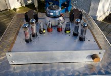
Amazed at how good this continues to sound. Big clean sound, acres of power and silent. Very happy with it. I'd find it hard to take a apart to reuse the bits - in fact I must tidy up the chassis, I used toroidals for the b+ and heaters and they need to be covered in.
As an aside, I have tried EL34s, KT66 and KT88 in this amp. All sound good with I think the KT88s beng the most neutral. They are of course under biased ( I didn't want to run more current as the OPT might not take it).
But here's something I found out in my trials. The KT88s have a metal ring that is connected to one of the grids in the tube. In this amp, that means that this exposed metal ring is at full b+ voltage. One to watch out for!!
Fran
Actually, pin 1 on the KT88 is unused and tied to the metal base. However in an amp wired to also use EL34 in triode mode, pin 1 is typically connected to pin 8 (cathode) on the socket, so you would have the cathode voltage there, but not the full B+.
Yep - this is an el34 amp that has the suppressor grid (el34 pin 1) connected to the b+ via a 1k resistor. So when you stick in a kt88/6550 which has that metal shield connected to pin 1 then the shield sees the full b+.
No biggy once you know and can be safe.
Fran
No biggy once you know and can be safe.
Fran
Are you sure that it is not the screen grid that is tied to the B+ through the resistor? The suppressor grid should be tied to the cathode.
Last edited:
I see your schematic now woodturner-fran, nevermind😱
Are you sure that it is not the screen grid that is tied to the B+ through the resistor? The suppressor grid should be tied to the cathode.
- Status
- Not open for further replies.
- Home
- Amplifiers
- Tubes / Valves
- A good sounding EL34 PP sch please