1K resistor
Hi,
I mean this one.
Best,
Audiofanatic 😉
Hi,
I mean this one.
Best,
Audiofanatic 😉
Attachments
Last edited:
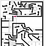
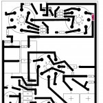
Here is an up to date layout of the schematic that I etched...
The only thing I did before etching is make the ground traces a little wider with a sharpie.
I still had to bend the octal socket leads around a little to get them to fit nicely for soldering.
Oh, and I did not adjust the grid stopper as advised in the above post yet either....
You may also want to draw a little more "meat" for the B+ inlet - I went from PSU to board 1 then from board 1 ran a wire to board 2...did this for ground also...
I also since moved the initial power resistors from the bottom of the board to the topside - may want to consider 3W or maybe 5W...I used 2W panasonics...
Attachments
Last edited:
cjkpkg - thanks for posting this!
I have some dynaco output iron gathered for this, 8k impedance and 4&8R taps. Good for 80mA a side so I'm hoping they will be good enough for this amp. I'll have to decide yet on whether to go PCB or just P2P, have to see what sockets I have!!
Fran
I have some dynaco output iron gathered for this, 8k impedance and 4&8R taps. Good for 80mA a side so I'm hoping they will be good enough for this amp. I'll have to decide yet on whether to go PCB or just P2P, have to see what sockets I have!!
Fran
No problem!
Yes I love this amp...I did the boards primarily because of the coupling caps...If I had chosen auricaps with insulated flexible leads I could have utilized my original aluminum plate idea...Buying the boards and 8 sockets was less than 8 auricaps though...
80mA should be just fine...I run 89 per channel and it sounds nice...
I am running the original feedback scheme with the voltage divider on the speaker outputs to ground. I want to try the 3K feedback resistor to the driver tube sometime.
Iron - check
Valves - check
Chassis - check
Most components - check
Ordered sockets tonight, hope to order the rest of the parts soon.....
Then to build!
Fran
Valves - check
Chassis - check
Most components - check
Ordered sockets tonight, hope to order the rest of the parts soon.....
Then to build!
Fran
Sockets delivered today...
Iron is all mounted, and power supply pretty much sorted. I will use DC heaters for the 6SN7s (12v with 2 tubes in series) and AC for the EL34s. I'm using those fairchild stealth diodes for the B+ rectification..... and probably russian K40y caps for the interstage caps.
Fran
Iron is all mounted, and power supply pretty much sorted. I will use DC heaters for the 6SN7s (12v with 2 tubes in series) and AC for the EL34s. I'm using those fairchild stealth diodes for the B+ rectification..... and probably russian K40y caps for the interstage caps.
Fran
Excellent Fran!
That is exactly how I am running mine...regulated DC on the 6SN7's and A/C on the EL34's.
I love the k40y9's.
That is exactly how I am running mine...regulated DC on the 6SN7's and A/C on the EL34's.
I love the k40y9's.
Did you ever go back and d the modified feedback with the pos and neg feedback to the driver 6SN7 cathodes?
I think I'll start off by doing mine standard, but maybe with the led on the input cathode. KISS and all that.....🙂
Fran
I think I'll start off by doing mine standard, but maybe with the led on the input cathode. KISS and all that.....🙂
Fran
I have not! Too many projects...I an knee deep in a CCDA phono stage that I am getting close on...
I ran it for a while with no feedback and it actually sounded quite nice. Now it has the 1K resistors off each of the speaker terminals running to ground. I just havent gone back to disconnect it too see if my memory is that good...
You might try it with no feedback first...then work your way up to running it back to the driver tubes...
He says that it is pretty high gain without feedback - did you notice that?
Good luck with the phonostage, I did the valve itch a while back, excellent sound and well worth it.
Fran
Good luck with the phonostage, I did the valve itch a while back, excellent sound and well worth it.
Fran
Progress so far: heaters wired, ps in place (crclc), iron all mounted. Ready to start the circuit next.
Cjkpkg: did you use one ccs for each output pair (bias set to ~80-100ma) with a balance pot or a single ccs per tube?
Fran
Fran
Yes, I used the LM317HV which is good to 57V - I think the cathodes come in around 40V which was pretty close to the limit for a standard LM317. One CCS per EL34 Pair with a balance pot. I think I had some 50ohm pots kicking around from another project.
89mA if I remember correctly...
89mA if I remember correctly...
Aaargh, I ordered up some LM317HV last night,..... added to the order just to bring it up to the minimum order level. What did I find in my parts box tonight? Grrrr....
Anyway, I've powered it up and it works. I've a big ole buzz going on though. I need to troubleshoot it a bit, but on first run all the voltages are there or thereabouts. Time to go tweak the grounding!!! Might need to shield the feedback and input wiring too.
Fran
Anyway, I've powered it up and it works. I've a big ole buzz going on though. I need to troubleshoot it a bit, but on first run all the voltages are there or thereabouts. Time to go tweak the grounding!!! Might need to shield the feedback and input wiring too.
Fran
I will have to check out my grounding scheme...Mine is very quiet...
however IIRC...
IEC ground to star ground
PSU ground to star ground
PSU ground to amp PCB ground
amp PCB grounds tied together
RCA ground to PCB ground
Feedback ground to star ground
CT of EL34 heater xformer to B+/4 tap on PSU board which is also the H- for the DC heaters on the pre/driver tubes
however IIRC...
IEC ground to star ground
PSU ground to star ground
PSU ground to amp PCB ground
amp PCB grounds tied together
RCA ground to PCB ground
Feedback ground to star ground
CT of EL34 heater xformer to B+/4 tap on PSU board which is also the H- for the DC heaters on the pre/driver tubes
Need to go over it again. I think though that a ct heater for the EL34s doesn't go to 1/4 B+ normally though? Doesn't it just go to ground? I know I made another booboo - I wired the AC EL34 heaters out of phase.... should have been in phase so that it would be cancelled in the output Tx.
I'm using a buss ground with the low current grounds at one end and the high current grounds at the other, this high current end is tied back to main reservoir cap ground. Worked really well before for me...
So there's a few things to sort...
Fran
I'm using a buss ground with the low current grounds at one end and the high current grounds at the other, this high current end is tied back to main reservoir cap ground. Worked really well before for me...
So there's a few things to sort...
Fran
The hum is largely under control. Turns out the EI transformer I was using for the 6SN7 heaters was the culprit. No matter how I tried to position it, the hum was there. I subbed in a 12V toroidal and the hum is much reduced. Probably don't have it to horn levels yet, but its very close to being right.
Gonna be a few days until I get back to it unfortunately!!!
Fran
Gonna be a few days until I get back to it unfortunately!!!
Fran
Hi,
I have a new issue - one that I haven't come across before. I have quite a bit of hiss in one channel. I've built the amp as per the schematic with 2 changes: A pair of red LEDs on the cathode of the input 6SN7 (giving me 3.6V) and a simple LM317 ccs on the cathodes of the EL34s (set to 83mA for the pair). Voltages check out across the amp within a few volts of predicted.
Through trial and error, I have found out that the hiss completely disappears if I touch my DMM probe off the back of the LM317HV. Take the probe off, and gradually the hiss comes back up (over 5 secs say). The LM317s are just sitting in mid air inside the chassis, with some short wires from the valve socket to the 20R pot and then to the LM317. Both channels are done this way, but only 1 hisses. Both are fairchild LM317HV.
Any ideas?
Fran
- Status
- Not open for further replies.
- Home
- Amplifiers
- Tubes / Valves
- A good sounding EL34 PP sch please