....Bob and I could go on all week until cows come home and even then .......
You'r doing fine. Things we all need to discover. Got my fingers crossed for your progress.

Build a new one. It will save time and money. You will be more experienced (trying to be positive here).
Fresh PCB. Better calculate all possible matters out of the situation (or how that is said in english).
New chances, new possibilities but I tell you the feeling when it works straight after connecting it is that of being invincible. Well at least for a few minutes 😉
Sorry Bob, I wished that your example would have worked flawlessly. We forget about the first one OK ?
New chances, new possibilities but I tell you the feeling when it works straight after connecting it is that of being invincible. Well at least for a few minutes 😉
Sorry Bob, I wished that your example would have worked flawlessly. We forget about the first one OK ?
Last edited:
"Go Directly To Jail - Do not collect $200." 🙁
As I've said in PMs and in posts, there are going to be many within the large number of buyers who will struggle with this build due to it's delicacy and SMD base. Nothing has been lost from my perspective as my efforts and failures may help drill down on some areas that require special attention. I have built several pieces with lots of surface mount parts, but this one is a little tricky. IMO - That's the beauty of diyAudio group efforts.
Onward & Upward.😀
Attachments

Last edited:
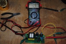
Success with the PSU after i got the correct transformer. I need another Mouser order to get a few parts - missed the 3.3 regulators. 🙁
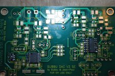
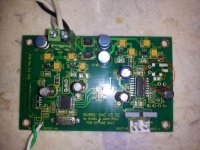
Soldered the 2 ICs and the resistor array (tough). Not pretty but I think I got it. SMD newbie 😀
Soldered the 2 ICs and the resistor array (tough). Not pretty but I think I got it. SMD newbie 😀
Attachments
You americanos always seem to think you can achive anything don't you ? 😉 I think this project is certainly not for beginners and also not for first time SMD guys. There is a very high chance it will not work as you really need experience to build this one.
The thing is that those that are the least experienced also are the ones that complain the most when it does not work 😀
Still it does look OK for a first SMD job. I can tell the XO is a real tough one. I would use larger pads if a rerun of boards would be done (which we don't).
The thing is that those that are the least experienced also are the ones that complain the most when it does not work 😀
Still it does look OK for a first SMD job. I can tell the XO is a real tough one. I would use larger pads if a rerun of boards would be done (which we don't).
Last edited:
I'm giving up on what I have.
Ordering new:
Q1
Q2
C28
C34
ES9023
C17
R7
Any other suggestions?
Bob,
troubleshooting an electronic circuit is about understanding that circuit and how it works before just changing parts here and there.
If i remember well you have a low voltage on pin 11 of ES9023 meaning 50mhz clock is not present.
The 50mhz clock can work (during tests only) also without C17 or you can put a ceramic 0.1-1uf and with R7 shorted. During troubleshooting when i was almost sure my 50mhz Xo is fried i used a 12mhz one a had on my drawer,maybe you have an XO >12mhz.
Also passive parts can be measured before just exchanging them.
Hope this was helpful!
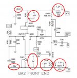
@bcmbob: I am wondering about your readings at the XO in post #240. The enable pin shows 0V. According to FOX HC73 Datasheet open pin should enable the XO, however "high impedance" path to low (GND) will disable the output! You should definately keep your PCBs clean. Better to set this pin high (connect to 3.3V).
Not sure about the voltage readings at the clock and I2S lines. Doesn't the reading depend on the bandwith of the measurement device? Might be better to scope the signals if possible or don't care at all Just a thought 🙂
Not sure about the voltage readings at the clock and I2S lines. Doesn't the reading depend on the bandwith of the measurement device? Might be better to scope the signals if possible or don't care at all
Just a thought 🙂Bob,
troubleshooting an electronic circuit is about understanding that circuit and how it works before just changing parts here and there.
Hope this was helpful!
Therein lies the rub
IMHO, there isn't enough information on the distributed schematic I have to follow the flow of the circuit. I completely understand the position of JP and Subbu in not wanting the flamer attack on a published schematic. That does however, leave the project open to a lot of "hunt and peck" debugging. I'm still fully committed to following through to a successful build of this DAC, but decided to replace some parts more out of frustration caused by not knowing what and where to probe than a shot at an easy fix.
I have and will continue to create some aids that hopefully give the builder a clearer understanding of what to look for along the signal and power paths, but that hasn't gelled yet. I suspect much can be learned by digging into the earlier version threads and digesting a few manufacturer's data sheets. That can be fun and instructive but many don't/wont follow that path. My biggest fear is again, many of the 500+ potential builders may have misinterpreted what was meant by "advanced level" project and that will lead to lots of unhappy campers. I hope I'm completely wrong - and also am willing to do what I can to help clear away some of the pitfalls that were not anticipated. Some may consider it unnecessary spoon feeding but I would love to see something like the following two examples established for this project eventually.
F5 Build thread.
MyRef Build Tutorial
FE SMD Soldering
Might could happen with a dedicated group effort,

Last edited:
Bob, i need to google for your native american expressions used 🙂
I do not want to comment JP decisions but i still believe my last post is very useful for your situation.
What other info do you need besides schematic that i fwd to you and datasheets of WM an ESS chips, tell me if can help you more.
I my opinion this dac is a very simple. plain datasheet implementation of a dac can be but a very careful one with good decouplings and regs.
Other helpful advice that i can give it for you today is to pick I2S signal after WM8804 and feed the Ak4396 DAC that you already have. In this way you are sure that your WM 8804 is working.
For that you need to desolder R4,R5,R6 form Subbu dac and also desolder one terminal of every correspondig resistors from 2496 DAC to break the I2S communication between Cs8416 and AKM 4396.
I'm almost sure that your XO is not well sodered or already fried from heat.
Sorry, too late.🙂 Pieces removed and sent to that big PCB in the sky.😉
I'm ordering a complete BOM plus duplicates of the components I trashed. Should arrive by Thursday and will pick up then.
P.S. What American slang needs definition? If you are referring to the "Go to jail..." thing - In the board game Monopoly one can draw a card that prevents you from landing on a spot (property) that you can buy with play money. I'ts a phrase that is used widely and generally means - bad luck of the draw and a need to start your game plan anew. 😀
Attachments
Last edited:
In this case you should order also a clock like this one: ACHL-12.000MHZ-EK ABRACON | Mouser
just to test before soldering the smd one. Test only 44.1khz files with 12mhz xo.
In this way you can be sure everything else is working.
just to test before soldering the smd one. Test only 44.1khz files with 12mhz xo.
In this way you can be sure everything else is working.
😕 Not helpful.You americanos always seem to think you can achive anything don't you ? 😉
How does one get experience? Someone who tries and fails is way ahead of someone who does not. Worse thing that happens, you are down some time and money.
I would also recommend this SMD kit for $10. I did it before attempting
SMD Soldering Practice Kit
I agree with you Bnoorish but after try and fail one should understand why he failed. Luckily parts are cheap and easy to obtain in these days.
...
What other info do you need besides schematic that i fwd to you and datasheets of WM an ESS chips, tell me if can help you more....
Don't know if it is even possible with a design as sophisticated as this DAC, but here is an example from a Pass project.
Attachments
Last edited:
- Home
- Source & Line
- Digital Line Level
- Build thread - building the Subbu DAC V3 SE