It depends on how long it is switched on for and if the case has openings for airflow.
I used a similar setup in a pc case and after a couple of hours of high power I couldn't bear my hand on the pc case. So I fitted a couple of fans and it was fine after that.
Well, if he's gonna listen only reggae and stays away from techno, then fans are no needed.
/me joking 😉
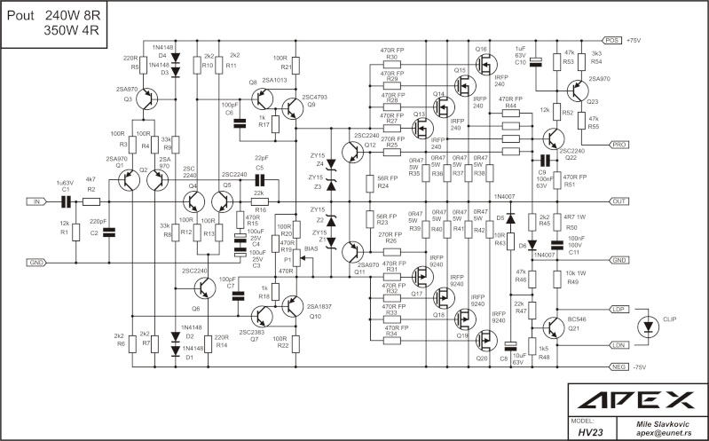
Mile, what do you think about this? Reducing distorsions significantly? I'm not completely understand what can I add? Sta mislis o ovome? Svidja mi se ono o drasticnom smanjivanju izoblicenja, ali mi nije bas jasno sta treba da dodam?If you want to reduce distorsion significantly, you could add another set of transistors identical to Q8, Q9 connected to R11 in the same way Q8 and Q9 are connected to R10. The collector of the "new" Q9 connected to ground. The emitter of "new" Q8 connected to the old Q8.
And the same for the negative side. This way, the VAS is configured as a differential amp and is very likely to produce severly improved linearity. I will try this in my own amp soon, but the sims show very promising results.
🙂
Mile, what do you think about this? Reducing distorsions significantly? I'm not completely understand what can I add? Sta mislis o ovome? Svidja mi se ono o drasticnom smanjivanju izoblicenja, ali mi nije bas jasno sta treba da dodam?
This is old forgotten design, many improvement is possible but I don't want get back to redesign HV23, I want keep it simple. If someone want to upgrade this amp please just go ahead.
Regards
what else would you suggest to do instead HV23 and to use it´s output mosfets and power supply?
what else would you suggest to do instead HV23 and to use it´s output mosfets and power supply?
There is nothing better than HV23 if you want to use IRFP240/9240 mosfets for amplifier.
Regards
excuse me for off-topic:is there a thread of apex d200 on this forum,Mile?
found it found it,found it...
.
sorry for OT once again! 🙂
hi apexaudio kan we switch the bc327 and the bc337 to bc639 and bc640 in the hv350 thanks
Yes but pins are different
Redrawing mistake. 2N5551 and 2N5401 wrong notification, corect on this schematics. 2SC2383 replaced with MJE340, 2SA1013 replaced with MJE350 in newer version both are OK. 2SB861 and 2SD1138 in VAS can be used too.
Hello apex,
but if you use 2sa1013, 2sc4793, 2sa970, 2sa1837, 2sc2240, as indicate in the first electric scheme HV23, I have problems?....

Hello apex,
but if you use 2sa1013, 2sc4793, 2sa970, 2sa1837, 2sc2240, as indicate in the first electric scheme HV23, I have problems?....
No problems, your pcb is for this transistors. Go to post #470
Last edited:
No problems, your pcb is for this transistors. Go to post #470
ok ... thank you.
a question, there is a point on the pcb with the name "protect", what is its function?
ok ... thank you.
a question, there is a point on the pcb with the name "protect", what is its function?
Send signal to PSU7 and disconect speakers if amp is overloaded, but amp can work without connect this point.
Send signal to PSU7 and disconect speakers if amp is overloaded, but amp can work without connect this point.
Thanks...

HV23 ampli
Hello apexaudio,
I have found that these differences between electric circuit and pcb, on the wiring diagram, R20 is 100R and 82R PCB layout? R49 on schematic dielectric is 10K1W, PCB is 1W6K8? and diode 1N4007, 1N4004 PCB is it? Using the values shown on the schematic diagram?
thanks
Hello apexaudio,
I have found that these differences between electric circuit and pcb, on the wiring diagram, R20 is 100R and 82R PCB layout? R49 on schematic dielectric is 10K1W, PCB is 1W6K8? and diode 1N4007, 1N4004 PCB is it? Using the values shown on the schematic diagram?
thanks
Hello apexaudio,
I have found that these differences between electric circuit and pcb, on the wiring diagram, R20 is 100R and 82R PCB layout? R49 on schematic dielectric is 10K1W, PCB is 1W6K8? and diode 1N4007, 1N4004 PCB is it? Using the values shown on the schematic diagram?
thanks
Use any of this values.
Use any of this values.
hi,
Use only the values indicated on the schematic diagram?
hi,
Use only the values indicated on the schematic diagram?
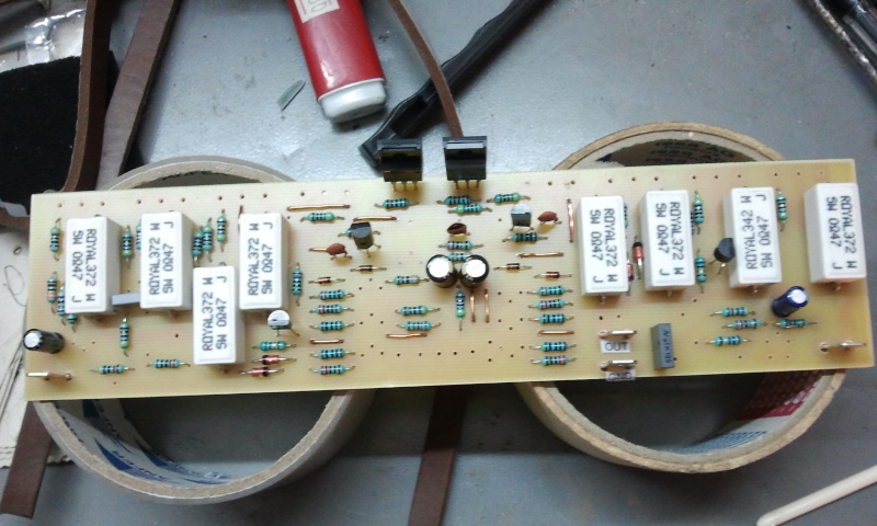
i did HV23 by the schematics and it works all right. the thing you should take care is to match its input transistors (all PNP and NPN) as close as possible to get small dc-offset on the output, AND PAY CLOSE ATTENTION to a transistor pin-out,those BC6xx and BC3xx have a diferent pin-out.
i did HV23 by the schematics and it works all right. the thing you should take care is to match its input transistors (all PNP and NPN) as close as possible to get small dc-offset on the output, AND PAY CLOSE ATTENTION to a transistor pin-out,those BC6xx and BC3xx have a diferent pin-out.
Thank you,
I'm building as indicated on the electrical schematic, with the same values. You who have already built, how to be sound?
- Home
- Amplifiers
- Solid State
- MOSFET Amplifier IRFP240/IRFP9240