Does anyone know of a simple Cap Multiplier for just the front end that could be used on this amplifier? Possibly one that could be incorporated into the board. There are some out there that I have seen, but not high enough voltage. Any thoughts?
Does anyone know of a simple Cap Multiplier for just the front end that could be used on this amplifier? Possibly one that could be incorporated into the board. There are some out there that I have seen, but not high enough voltage. Any thoughts?
Chris, there is no high or low voltage cap multipliers. It is important to use a transistors with high enough voltage for them, even if during operation the voltage drop on the multiplier is very low, during turn on and off it will be uder voltage stres.
Attached simple + and - cap multipliers.
Damir
Attachments

The K multiplier seems to be good. Rated for 25mA to 100mA.
Kean should be able to offer advice for HV operation.
Kean should be able to offer advice for HV operation.
The K multiplier seems to be good. Rated for 25mA to 100mA.
Kean should be able to offer advice for HV operation.
Yes I know about Kean cap multiplier, but I think that the complication is not nedeed, the simpler one I showed is more than good enough.
The K multiplier seems to be good. Rated for 25mA to 100mA.
Kean should be able to offer advice for HV operation.
I asked him, Keantoken, about one sometime ago. Hopefully he will respond, as Dadod says, it is not that complex. I will incorporate it into the board.
Thanks for all responses.
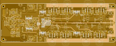
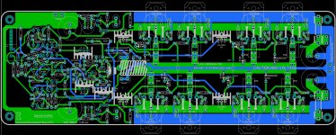
Closing in on the final, Comments Please.
Chris this is very nice, but two things first. Could you give more contrast layout(to be easier to check) and could you change laterals nomination? 2SJ49 and 2SK134 are TO3 types.
Chris this is very nice, but two things first. Could you give more contrast layout(to be easier to check) and could you change laterals nomination? 2SJ49 and 2SK134 are TO3 types.
What should the outputs be named?
The board is not done. I am just trying to get the parts in the right position, and adjust overall topology and trace width.
Do you want to use a heat sinked 10 watt resistor for the 480?
Here is a more convention view.
Hope I am doing good enough to match the potential of the board.
Attachments

What should the outputs be named?
The board is not done. I am just trying to get the parts in the right position, and adjust overall topology and trace width.
Do you want to use a heat sinked 10 watt resistor for the 480?
Here is a more convention view.
Hope I am doing good enough to match the potential of the board.
I think that I've written to you about that, 2SK1058 and 2SJ162. And I've gave you olso some other more then standard wattage resistors as one in output zobel, R36 should be 2W and R9 should be 1W or better 2W. And of course that 480 ohm in the feedback I would like to have others opinion.
Dont forget separate frontend signal ground(I think I sent to you one schematic with those grounds marked).
What do you think the layout is going to be ready for inspection?
Damir

Depends on where the MAG is located and what route the speaker current follows.Isn't the GND trace to the Spk-GND header a little undersized?
Here are those changes
I think that I've written to you about that, 2SK1058 and 2SJ162. And I've gave you olso some other more then standard wattage resistors as one in output zobel, R36 should be 2W and R9 should be 1W or better 2W. And of course that 480 ohm in the feedback I would like to have others opinion.
Dont forget separate frontend signal ground(I think I sent to you one schematic with those grounds marked).
What do you think the layout is going to be ready for inspection?
Damir
Hi Chris, you forgot R36 and R9 from above post, please make bigger footprint for those resistor to accomodate bigger resistors.
One more thing, don't connect the return loudspeaker track to the power ground, make separate faston connector and from that one it will be connected to the star ground outside the PCB.
Also jumper 1(same for minus pole), please connect the big cap to the midle pin, in this case it is possible to choose between separate frontend power via C multy and connection to the common power via C multy or jusr RC filtering.
All changes circuled in red.
Damir
Attachments
Hi Chris, you forgot R36 and R9 from above post, please make bigger footprint for those resistor to accomodate bigger resistors.
One more thing, don't connect the return loudspeaker track to the power ground, make separate faston connector and from that one it will be connected to the star ground outside the PCB.
Also jumper 1(same for minus pole), please connect the big cap to the midle pin, in this case it is possible to choose between separate frontend power via C multy and connection to the common power via C multy or jusr RC filtering.
All changes circuled in red.
Damir
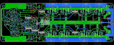
What would be a good foot print size for R36 and R9 in mils 7, 8, or 9?
Can the ground be next to the speaker ground I have on the board and eliminate the big trace I have running under the output Bus?
What would be a good foot print size for R36 and R9 in mils 7, 8, or 9?
Can the ground be next to the speaker ground I have on the board and eliminate the big trace I have running under the output Bus?
I am not sure, but put it between 15 mm and 20 mm. My Sprint software is 5.0 and I don't have a macros you are using for a resistors.
Live the speaker ground trace as it is, better to have it parallel to the big output trace.
I gave you both, just in case...😀
Keep going, I am in correction mode now.
Sorry my mistake, not R22 it was OK, but R9.
You did not follow my recomendation not to connect the loudspeaker ground track to the power ground!! And it looks that it touching trough the board platted holes for the output resistors.
Last edited:
- Home
- Amplifiers
- Solid State
- 200W MOSFET CFA amp