Member
Joined 2009
Paid Member
I was actually surprised at how close most of the amps sound to each other once the output is equalized.
shhhh! - that's a secret only a few people know
")
The higher the bias the better the GB150 sounds to me. Mine are set to >200mA per pair.
I attribute the lack of "sizzle" to the high psrr of the design. Have I tested for it? No. But everytime I've mod'd my amps to improve the supply or psrr the high end is better.
I am with you for the High bias of mosfet. But I am not sure it is that simple for the PSRR..
I can find examples of low PSRR amps with lack of "sizzle" (I suppose you mean lack of sibilance) . These are : Hiraga super class A, F5, F5 Juma and NX amps. These are all CFA amps with low PSRR.Or maybe I confuse your sizzle with sibilance...:

Fab
Member
Joined 2009
Paid Member
fyi - - There's no reason for the nx amp to have low PSRR - I don't believe it has low PSRR. I've looked at the topology, it's a common approach and with the RC filters in the power rails to the front-end it should have good PSRR. The SKA amp is a different topology and can not use the RC filters.
The other amplifiers you list are Class A and place different demands on the power supply than a Class AB amplifier.
The other amplifiers you list are Class A and place different demands on the power supply than a Class AB amplifier.
It will actually work fine up to a little over 50V, even with the original components. It just needs the Schottky diodes swapped out for something like the MSRF860....The Mr E/PMI CM will not go above about about 42V. ...
The Schottky diodes work best at the lower voltage ranges, and were selected for their low forward voltage drop. Their maximum reverse breakdown is 100V so the rails have to stay a couple volts below that.
I have been running the supply well above 50 with slightly different components, most important being the pass transistor, but I have not tested as thoroughly as I did the original w. the components as listed in the BOM.
For now, you can assume that with the MSRF860 rectifiers, or any similar rectifier diode, 50V nominal is fine, plus the inevitable 5% to allow for load regulation on a typical transformer. I think you should also have the taller heatsink for the pass transistor but that depends on the intended use.
A comparison to the DX supply is not really fair to either design. They may both be Cap Multipliers, but after that, they are very different.
Hi Pete,
That is good to know. I actually used MSRF860's in both my CM's. For some reason I thought it was the transistors that couldn't handle it.
At any rate, the transformer I am using for the SKA is a 40-0-40VAC so I have to turn down the regulator to +/-50V. I'm not sure how well the CM will work for that.
According to Greg Ball, the SKA was designed to work with poor PSU's so maybe it doesn't matter.
fyi - - There's no reason for the nx amp to have low PSRR - I don't believe it has low PSRR. I've looked at the topology, it's a common approach and with the RC filters in the power rails to the front-end it should have good PSRR. The SKA amp is a different topology and can not use the RC filters.
The other amplifiers you list are Class A and place different demands on the power supply than a Class AB amplifier.
You are correct but still the NX amp has lower PSRR than if it would be VFA or compared to other VFA amps. I had VFA amps (diff input CFP cascode with very high impedance CCS) with very big PS and they had more sibilance than the ones I mentioned. I just want to highlight that the high PSRR is probably not a guaranty to get low sibilance.
By correlation I could easily say that the Hiraga , F5 and SKA have all an inverted output stage so this is the reason for low sibilance. But I can not say that because it is not a cause-effect relation.
Fab
That may be too high. 40VAC will give you ~1.4 x 40V unregulated voltage, 56V, plus 5% allowance for load regulation. I designed for a low forward voltage drop, and low power loss in the CM filter.At any rate, the transformer I am using for the SKA is a 40-0-40VAC so I have to turn down the regulator to +/-50V. I'm not sure how well the CM will work for that.
The "Improved" Cap Multiplier from MrEvil's thread, you should have a transformer which is in range for the intended supply voltage. The reasons for using MrEvil's design, were not just good filtering, but also high efficiency/low loss, excellent response to changing current demand, modest cap values and physical size. The voltage drop for good performance can be as little as 0.5~1V. If you use it with this amp, it should be used as intended. Think of the filter in the supply as an engine for a sports car.
Carlos's DX supply is better for dropping lots of voltage, it is designed like a tank, and looks like it can handle just about anything!...
Member
Joined 2009
Paid Member
On the bias issue, I believe owners have found the higher the bias the better the sound, with the main limiting factor being that the older designed boards (pre 0.15R's being added) had more bias fluctuation so builders had to be careful that bias didn't run away. With the R's added you can be more adventurous, I believe (I only have the older design at the moment).
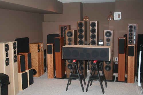
I can say without any issue at all my SKA amp drives ny speaker so far I have thrown at it..
Some of the designs use a low 3.8ohm in the bottom end of the design down into the 24hz range and my amp has had no issues at all.
And I will say the photo only shows a small margin of what has been played with my SKA amp.
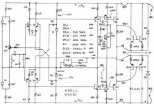
Is it a coincidence that the Krell KSA has similar initials to SKA and the schematics have a lot in common ?
maybe not
I think he once was working as service/repair man on top brand amplifiers
SKA sponsored Audio Forum - Eidetic GB2b
A little bit of Greg's history in this thread.
A little bit of Greg's history in this thread.
The Krell looks like a very conventional symmetrical Lin design with emitter follower output. Nothing in common with the SKAIs it a coincidence that the Krell KSA has similar initials to SKA and the schematics have a lot in common ?
Member
Joined 2009
Paid Member
I was thinking about the front end, the complementary LTPs with constant current tails and complementary emitter follower buffered VAS; similar dc-offset adjustment scheme. After that they're quite different as you say but if you look at them through your bad eye then there are still these similarities. Terry said his GB150 sounded more like his Krell clone than any of his other amps.
Last edited:
Hi SKA builders!
The PCBs from JIMS Audio have arrived, it's time to build this wonderful amp. I already have a +-35V, 500VA toroid and a power supply board with 60k mF elcos. I wanna build the amp as cool and as compact as possible.
Dear PaoloPT!
There are a few questions for you, if you allow.
I checked the loudspeaker portection on pix, what you've uploaded in builders thread, and it seems to work without external PS.(?) What protection do you suggest?
Is it worthwhile to order matched output fets from ebay?
A have tons of BC546 - 556 already. Could I use them in LTP's? (twisted and isolated legs, of course) or are there any reason to avoid them in JIM's PCB?
Thank You for your answers and congratulations for your amplifiers.
Cheers
Alex
Hi egra,
My speaker protection is powered by the transformer's secondary winding, 0-35V AC.
Any speaker protection will be fine, you can check the one at DiyAudio store.
Be careful when soldering them, they have EBC pinout and pcb was made for the 2SC/SA which have a BCE pinout, so you have to twist their legs.
This is a very good sounding amp, I'm sure you will enjoy the results very much!
Good luck with your build!
My speaker protection is powered by the transformer's secondary winding, 0-35V AC.
Any speaker protection will be fine, you can check the one at DiyAudio store.
Yes, you have to match the output IRFP's at 10mV VGS or better. This is very important!Is it worthwhile to order matched output fets from ebay?
Absolutely! For better results use the "C" grade ones - BC546C and BC556C.A have tons of BC546 - 556 already. Could I use them in LTP's?
Be careful when soldering them, they have EBC pinout and pcb was made for the 2SC/SA which have a BCE pinout, so you have to twist their legs.
Thank you, egra.Thank You for your answers and congratulations for your amplifiers.
This is a very good sounding amp, I'm sure you will enjoy the results very much!
Good luck with your build!
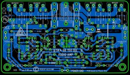
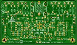
Wow, that is a beautiful layout!..... single layer PCB , first try .......
Regards Alex

- Home
- Amplifiers
- Solid State
- SKA GB150D now public domain...