The great thing about "bell ringer" jigs with in-situ snubbers is, that you can directly observe how well or how poorly this specific individual snubbber actually works. You can install capacitor #1, turn on the bellringer, and dial the Rsnub to find the least objectionable waveform. If you're happy, boom. Done.
If you're not happy, if the least objectionable waveform is still objectionable, then remove capacitor #1 and install capacitor #2 in its place. Turn on the bellringer and dial the Rsnub to find the least objectionable waveform with this new capacitor. Happy? If so, have a pint. If not, proceed on to capacitor #3, and so forth.
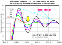
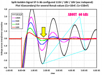
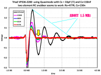
I copied some scope traces from the Quasimodo design note, to show a range of possible omega_n values at which your snubbers might have to operate. (Of course, your transformer and your snubber might have an omega_n above the highest shown here, or below the lowest shown here. These scope traces are mere anecdotes. Individual data points. Nothing more. Your mileage may vary.)
You could do some research to find out which type(s) of surface mount capacitors the RF crowd uses, at these kinds of frequencies. Or the high speed data acquisition crowd. Or, at the intersection of the two disciplines, the software defined radio crowd.
Or else you could just be an empiricist. Install the cap, turn on the bellringer, twirl the potentiometer, look at the scope trace, and ask yourself: is this good enough, in my opinion?
If you're not happy, if the least objectionable waveform is still objectionable, then remove capacitor #1 and install capacitor #2 in its place. Turn on the bellringer and dial the Rsnub to find the least objectionable waveform with this new capacitor. Happy? If so, have a pint. If not, proceed on to capacitor #3, and so forth.
I copied some scope traces from the Quasimodo design note, to show a range of possible omega_n values at which your snubbers might have to operate. (Of course, your transformer and your snubber might have an omega_n above the highest shown here, or below the lowest shown here. These scope traces are mere anecdotes. Individual data points. Nothing more. Your mileage may vary.)
You could do some research to find out which type(s) of surface mount capacitors the RF crowd uses, at these kinds of frequencies. Or the high speed data acquisition crowd. Or, at the intersection of the two disciplines, the software defined radio crowd.
Or else you could just be an empiricist. Install the cap, turn on the bellringer, twirl the potentiometer, look at the scope trace, and ask yourself: is this good enough, in my opinion?
Attachments
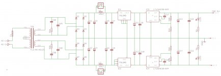
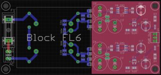
OK, here is version 0.3:
- Added optional snubber components.
- Added optional jumpers to bypass the inductors.
- Changed C11-14 to D size Panasonic caps so could be 22-47uF.
- Made PCB wider to increase distance around mains traces.
L1/2 = Panasonic INDUCTOR, 1812 CASE, 47.0UH
C1-6 = Panasonic FC series 35V, 470UF
C7-10 = Kemet CAPACITOR, 1206, 220NF, 50V, X7R
C11-14 = Panasonic FP series CAPACITOR, D CASE, 47uF, 25V
C15/16 = Wima Polyester 1812, 0.1UF, 63V
C17/18 = Reg BYP caps, TDK, 1206, C0G, 100V, 10NF
R1A/B = Panasonic 240R, 0805, 0.1%, 0.125W
R2A/B = Panasonic 2K4, 0805, 0.1%, 0.125W
Cs = 1210 package
Cx = 1210 package
Rs = 1206 package
Questions!
Is it OK to put the snubber components directly under the transformer?
Should I ground one corner so it can be easily connected to the chassis?
Attachments
Here is a very good paper about film capacitor characteristics:
http://www.epcos.com/web/generator/...__en.pdf;/PDF_GeneralTechnicalInformation.pdf
http://www.epcos.com/web/generator/...__en.pdf;/PDF_GeneralTechnicalInformation.pdf
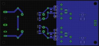
In your layout, you need to keep the AC pairs RIGHT next to each other, everywhere possible. Otherwise, you are making hum-transmitting antennas. So you need to determine the minimum-allowable gap between traces carrying various levels of AC voltage or current and make the gaps not much larger than that, everywhere possible. That should include the incoming AC mains, the secondaries, and everything up to the reservoir caps. And, since the current will in general be dynamic (time-varying) in the DC pairs, those should also have the minimum-allowable gap between them, everywhere (a ground plane or two makes that very easy to implement).
It looks like the LT1761 is not a good choice for a power supply rated for 100 mA, since that is the 1761's rated upper limit (and it sounds like maybe that's only for up to 10 Volts output). The other one you chose, the LT1964, is rated at 200 mA.
You could look at others, such as the LT1962 (300 mA, 30 uV noise).
It would be nice if Linear had matching positive and negative ones. I guess you could match the LT3090 negative regulator (600 mA, 18 uV noise) with one of their positive low-noise 500 mA ones, if the low noise spec is important to you.
Nearly matching pairs are LT3015 and LT1963A in a variety of cases up to TO220 for 1.5A
Fully matching pairs (with ultra low noise @ 15.4uV) are the new Texas devices, TPS7A49xx and TPS7A30xx, rated at +/-36V and 150mA. I am now using these in my Marantz CDP upgrades.
You can buy an evaluation module containing both regs with all components soldered for $20 from the TI Store
Evaluation Module for TPS7A3001 and TPS7A4901 Low-Dropout Linear Regulator - TPS7A30-49EVM-567 - TI Tool Folder
OK I can bring them closer but only marginally. Bear in mind that the transformer on the PCB is only 50mm square so the distances we are talking about here are a couple mm. I can't see how I can bring the AC pairs closer together without doing something silly like having the fuse horizontal.In your layout, you need to keep the AC pairs RIGHT next to each other, everywhere possible.
I already have a ground plane on each side so I can't really get it any better?in the DC pairs, those should also have the minimum-allowable gap between them, everywhere (a ground plane or two makes that very easy to implement).
I don't get this. Why? Where do you get 10V from?It looks like the LT1761 is not a good choice for a power supply rated for 100 mA, since that is the 1761's rated upper limit (and it sounds like maybe that's only for up to 10 Volts output). The other one you chose, the LT1964, is rated at 200 mA.
Believe me, I've looked! The LT1962 only comes in 8-Lead MSOP Package. Do-able but not the easiest IC to solder!You could look at others, such as the LT1962 (300 mA, 30 uV noise).
I know. None of them match in specs and they all come in different packages.It would be nice if Linear had matching positive and negative ones.
I know but I want to use SMD components and the only one LT3015 and LT1963A come in is 5 lead DDPAK which very large and overkill for what I want.Nearly matching pairs are LT3015 and LT1963A in a variety of cases up to TO220 for 1.5A
I know but they are not solderable by hand due to the 3x3mm size and the use of a power pad. The eval modules are fine but very large. If like these ICs and not keen on the eval modules you can take a look at the DIYINKH modules, they look quite nice.Fully matching pairs (with ultra low noise @ 15.4uV) are the new Texas devices, TPS7A49xx and TPS7A30xx, rated at +/-36V and 150mA.
The 10v was just in the description somewhere. The main problem is that the 1761 causes a lot more ripple than the other one, even at only 50 mA load. I think it's just a matter of using parts that aren't pushed to their limits.
I can't see 10V referenced anywhere? Let's forget that...
Is the ripple you mention in your simulation or is this from the datasheet? If it's from the sim, are you sure if it would behave like that in reality?
Is the ripple you mention in your simulation or is this from the datasheet? If it's from the sim, are you sure if it would behave like that in reality?
It's from simulation. It looks reasonable but I'm never sure of anything. It basically always gives about double the ripple, if you want them to respond at about the same speed.
I'm not even sure how important that is, since it will be down in the below-20mV range, anyway.
I just finally got the sim circuit working well last night, so I haven't done a lot with it yet. I finally had to replace the 7915 model with a Linear part, just to get it running well-enough, because I couldn't find a decent spice model for the 7915. But the same types of mismatch differences were evident even without the 79xx regs in the circuit. I'll upload the circuit model and some plots, tonight if possible, so you can see what I mean.
The LT1962, on the other hand, looked great, when I finally substituted it.
Last edited:
OK, thanks very much for your input thus far, I really appreciate it. I would be keen to see the plots if you have time to post them.
One thing I would like to question though: Do you think this design will be better than the standard LM317/LM337 design that is used everywhere? This is my goal and I'm hesitant to lose sight of this 🙂
One thing I would like to question though: Do you think this design will be better than the standard LM317/LM337 design that is used everywhere? This is my goal and I'm hesitant to lose sight of this 🙂
Have you thought about just using two identical positive regulators? You don't need a negative reg to make a negative rail.
OK, thanks very much for your input thus far, I really appreciate it. I would be keen to see the plots if you have time to post them.
One thing I would like to question though: Do you think this design will be better than the standard LM317/LM337 design that is used everywhere? This is my goal and I'm hesitant to lose sight of this 🙂
I'm sure that it could be better. But you would need to define the metric by which they would be compared. i.e. What are the measurable requirements and how is each one weighted? (just like you would in any optimization problem)
It would probably be relatively easy to compare them, in one simulation circuit where they run side by side. Simulations don't usually tell the whole story but for some things they are very good. You would want to build and measure, to really know. And then it comes down to how well each one is implemented. And it would probably also depend heavily on the application.
I am not an expert at these things, so maybe someone else will offer some more-knowledgable opinions or ideas.
I did but was kind of put off by the fact that NO ONE does this. You hardly ever see designs that use this method. Do you know why?Have you thought about just using two identical positive regulators? You don't need a negative reg to make a negative rail.
The problem is that I don't have any measuring equipment and to be honest I don't really have the room, time or inclination for getting that deep into the technical side. I'm not being lazy it's just that this is a hobby and I only have so much time and resources to spend on a PSU when I have other projects I want to get into as well!I'm sure that it could be better. But you would need to define the metric by which they would be compared. i.e. What are the measurable requirements and how is each one weighted? (just like you would in any optimization problem)
Calculating Creepage and Clearance Early Avoids
Welcome to the world of creepage and clearance, something a lot of DIYers are unaware of, but should follow for safety and to cover yourself in case of accidents or fire.
For home stuff use pollution degree 2 and always use the maximum voltage so use 400V ac for UK mains (RMS max 253, peak *1.414). As a guide 4mm.
You might want to be prepared to add pads for resistors between the rails and C15 and C16 (a resistor in series with each cap). I got oscillation with a square wave load current, without them. If they're later found to not be needed, you could install jumpers in place of the resistors.
Maybe I was wrong about the 1761. Or maybe the 1964 is just really good. Even with a 1962 in place of the 1761, the load-current-induced ripple is about twice as large, on the positive rail. And that's with larger negative rail ripple on the regs' inputs (after the pre-regs) in both cases.
Wow, what about the LT3032?! Oh, too small to hand solder (14 leads in a 4mm x 3mm). Bummer!
LT3032 Series - Dual 150mA Positive/Negative Low Noise Low Dropout Linear Regulator - Linear Technology
http://cds.linear.com/docs/en/datasheet/3032fd.pdf
I think I will simulate with it, anyway, to see if it has the same asymmetric load-induced ripple, in my circuit.
But maybe it's time to look into doing SMT reflow soldering with a toaster oven.
I'm sensing you're not quite sure 🙂 Also, correct me if I'm wrong, but the issues you are talking about seem like they could be quite minor (below -20mV range)? Remember, I'm not trying to build the best, just something better than the LM317/337.Maybe I was wrong about the 1761. Or maybe the 1964 is just really good.
I know! I thought it would be good too. I checked all the Linear regs and came to the LT1761/LT1964 pair because of their packages and good feedback in other threads on here.Wow, what about the LT3032?! Oh, too small to hand solder (14 leads in a 4mm x 3mm). Bummer!
I'm sensing you're not quite sure 🙂 Also, correct me if I'm wrong, but the issues you are talking about seem like they could be quite minor (below -20mV range)? Remember, I'm not trying to build the best, just something better than the LM317/337.
<snipped>
I was just trying to say that the larger positive rail ripple was apparently not because the 1761 was being pushed too hard. It's that way for all of the ones I've tried, including the LT1761-BYP, the LT1962, and even the LT3032.
And yes, the ripple is quite low level. So it might not matter at all to you. I was just curious about the asymmetry.
- Status
- Not open for further replies.
- Home
- Amplifiers
- Power Supplies
- A simple but low noise LT1761/LT1964 PSU design