Richard, good work indeed.
I think matching the diamond transistors and associated resistors is easy - 0.1% are readily available, and matched pairs of devices (10% hFE and 2mV Vbe) also sheep and plentiful from NXP, Rohm et al.
In a practical amp, 3 dB loop gain neither her nor there IMV.
As I remarked earlier, the diamond input stage DC stability is very good provided you run both the buffers and the level shifters at the same Ic and Vce.
Re the 'lytics' - I would prefer to avoid them and would thus not personally go for this topology in favor of the diamond. However, this does not detract from LC's elegant implementation despite the overt self promotion . . .
What is important is that both these designs are very simple, low feedback types that achieve low distortion, wide bandwidths and fast slew rates (nx- Amp, I don't know if this is correct for the LC design)
Richard, good work indeed.
I think matching the diamond transistors and associated resistors is easy - 0.1% are readily available, and matched pairs of devices (10% hFE and 2mV Vbe) also sheep and plentiful from NXP, Rohm et al.
In a practical amp, 3 dB loop gain neither her nor there IMV.
As I remarked earlier, the diamond input stage DC stability is very good provided you run both the buffers and the level shifters at the same Ic and Vce.
Re the 'lytics' - I would prefer to avoid them and would thus not personally go for this topology in favor of the diamond. However, this does not detract from LC's elegant implementation despite the overt self promotion . . .
What is important is that both these designs are very simple, low feedback types that achieve low distortion, wide bandwidths and fast slew rates (nx- Amp, I don't know if this is correct for the LC design)
Second stage; final design topology. What have we to choose from? Quit a lot of good ideas here to choose from. Sort to final 2-3 and only a short debate is neede unless something totaly new is brought forth we havent heard about already.
The floor mic is open.
Thx-RNMarsh
Last edited:
[just kidding]
Nice. Simple too. 🙂 Run a very detailed and thorough sim on it and get back to us next year.
[not really]
-RM
Nice. Simple too. 🙂 Run a very detailed and thorough sim on it and get back to us next year.
[not really]
-RM
Last edited:
If it has Holy Hooks for 'pure Cherry', this would solve the o/p THD too 🙂
Maybe double Rush cascodes but that's 4 extra devices
Until then, simple CFAs have an advantage over simple VFAs .. maybe down to 10ppm THD20k.
For lower THD, VFAs seem to have an advantage until we work this out. I don't think you'll see any advantage with Diamond i/p over 'simple' until we do.
But when we do, the supa CFA is likely to have a THD profile similar to a good VFA 😀
Now that the topic , not surprisingly , has switched from the input stage
to the other end of the amplifier where all the evils are actualy concentrated , i.e , the output stage , it wont take long before Cherry s NDFL concept will appear as the saving grace , although simpler designs than Edmonds/Ovidiu s PGP would be necessary given , as justly pointed by Waly,
the excessive complexity of such a design that do low distorsions ratios thanks to some NDFL but firstly thanks to its use of Bob Cordell s implementation of Hawksford s error correction.
As for NDFL , it requires preferably a VFA with vast amount of gain
as well as three or four voltage gain stages to implement two or three
nested feedback loops wich will really iron out distorsions, as per Cherry s
own words , since not only THD but more importantly IMD will also
be reduced to negligible quantity.
Attachments
which VAS/IPS interface?
I hope this doesn't mean you are abandoning us unwashed masses. Despite appearances, I pre 10 to unnerstan all your posts, Guru bcarso 😀
________________________________
Distortion mechanisms in da main VAS transistor
I suggested that instead of the idiotic VAS vs TIS naive 'linear-based' arguments we should ask if
clean current input gives clean current or voltage output
OR
clean voltage input gives clean current or voltage output
I did this for my #499 & #502 circuits (can't remember where I posted) and the answer is not surprisingly .. a bit of both with a bias towards clean Voltage amplification. So the correct name IS in fact VAS 🙂
I was expecting to see cleaner Current amplification especially for the simple #502 circuit. You might get different results from different circuits even with the same topology.
The Enhancer in #499, like most, isn't a perfect Voltage follower or Current Amp but something in between. It has resistors & other stuff that complicate matters.
Other stuff
VSSA, my 'simple' stuff, both versions of nx-Amp, have the i/p current across a load resistor whose voltage sets the VAS current. This is sensitive and needs careful tweaking. If we use a Current Conveyer (current mirror with precise gain) we can design the VAS current. But we are limited to sensible currents for IPS & VAS. If we want 1mA & 50mA, this sets the gain of the Conveyor to 50.
For the 1000+ current gain that an Enhanced VAS can provide, the currents in IPS & VAS become stupid.
In fact, this is also a limitation of VSSA, 'simple' & nx-Amp. Adding a enhancer to my #500 to get #825 reduces THD by less than 6dB cos the Loop Gain increases by less than 6dB
NAD3020 sets the VAS current using 2 resistors so isn't limited by this .. but we lose the symmetry that this august forum feels is necessary for CFA.
_____________
BTW, this 'symmetrical amp' problem is also there for VFAs. I believe Self discusses this in his new book. Anyone read the book and can comment?
Haven't mentioned Holy Hooks for compensation and interface to OPS.
Anyone have anything to add?
At last! A simple design from Brad 'waddya mean zillion transistors too many?' 🙂Perhaps the last one I will post 🙂
I hope this doesn't mean you are abandoning us unwashed masses. Despite appearances, I pre 10 to unnerstan all your posts, Guru bcarso 😀
________________________________
If I may add some info on this subject ... I don't have any good recommendations ... just points to watch. Firstly ..RNMarsh said:Second stage; final design topology. What have we to choose from? Quit a lot of good ideas here to choose from. Sort to final 2-3 and only a short debate is neede unless something totaly new is brought forth we havent heard about already.
Distortion mechanisms in da main VAS transistor
- If you voltage drive this, you get exponential Vbe vs Ic. Mainly 2nd with %=Vi in mV. In a 'symmetrical' amp, most of this should cancel out .. and pigs might fly. You get around this by current driving
- .. then you get hit by hfe varying with Ic. But this variation is usually less wonky than the exponential Vbe relation
- Ccb is modulated by Vcb and is probably the biggest contributor at HF. It's particularly bad if you current drive.
- the Early effect also shows some modulation but usually 'smaller' than modulated Ccb. If it wasn't modulated, it would be 'linear' and simply reduce the gain.
- Current drive gets rid of the exponential Vbe/Ic and replaces it with less yucky, smaller hfe changes. But you are wide open to modulated Ccb. This is what you get with LTP+CM into single VAS. It has known good performance except at HF
- A Blameless Enhancer does 2 things. Increases 'hfe' of the VAS giving loadsa extra Loop Gain. But this is accompaniend by another pole to muck up your stability.
- It also drives the main VAS device with a much lower Z & greatly reduces the effect of yucky Ccb
- Cascoding the VAS reduces yucky Ccb effects but doesn't give you loadsa Loop Gain. But in many VFAs, it might be the major THD mechanism.
- Voltage driving the VAS gives you more Vbe/Ic THD which you hope will cancel in the symmetrical amp. Having loadsa main VAS current helps.
I suggested that instead of the idiotic VAS vs TIS naive 'linear-based' arguments we should ask if
clean current input gives clean current or voltage output
OR
clean voltage input gives clean current or voltage output
I did this for my #499 & #502 circuits (can't remember where I posted) and the answer is not surprisingly .. a bit of both with a bias towards clean Voltage amplification. So the correct name IS in fact VAS 🙂
I was expecting to see cleaner Current amplification especially for the simple #502 circuit. You might get different results from different circuits even with the same topology.
The Enhancer in #499, like most, isn't a perfect Voltage follower or Current Amp but something in between. It has resistors & other stuff that complicate matters.
Other stuff
VSSA, my 'simple' stuff, both versions of nx-Amp, have the i/p current across a load resistor whose voltage sets the VAS current. This is sensitive and needs careful tweaking. If we use a Current Conveyer (current mirror with precise gain) we can design the VAS current. But we are limited to sensible currents for IPS & VAS. If we want 1mA & 50mA, this sets the gain of the Conveyor to 50.
For the 1000+ current gain that an Enhanced VAS can provide, the currents in IPS & VAS become stupid.
In fact, this is also a limitation of VSSA, 'simple' & nx-Amp. Adding a enhancer to my #500 to get #825 reduces THD by less than 6dB cos the Loop Gain increases by less than 6dB
NAD3020 sets the VAS current using 2 resistors so isn't limited by this .. but we lose the symmetry that this august forum feels is necessary for CFA.
_____________
BTW, this 'symmetrical amp' problem is also there for VFAs. I believe Self discusses this in his new book. Anyone read the book and can comment?
Haven't mentioned Holy Hooks for compensation and interface to OPS.
Anyone have anything to add?
Last edited:
Kgrlee -- what are you trying to recommend? Spit it out. Make a stand. be counted. best educated guess
would be ______ ?? C-Convey-VAS?
-Richard
would be ______ ?? C-Convey-VAS?
-Richard
Last edited:
Mr. Marsh, I'm new to this CFA game. Never burned solder on anything similar except for a very low noise application.Kgrlee -- what are you trying to recommend? Spit it out. Make a stand. be counted. best educated guess
would be ______ ?? C-Convey-VAS?
As I said, I don't have any recommendations .. only a pile of caveats. I'm hoping for guidance from this august group. They are the same caveats as for my VFAs but there, I've got Jurassic 'real life' to back up my recommendations.
Here I'm just guessing, playing at LTspice pseudo guru and hoping to inspire those with more experience to greater heights.
About the only thing I've 'recommended' is the 'simple' i/p instead of Diamond. Cos present CFA designs have low feedback, this usually gives 3dB better THD ... but for me, also 2 less devices 😀
I accept & understand Bonsai & your dislike for evil electrolytics but this choice is really small beer compared to the choice of VAS to interface with the IPS. I don't think Diamond i/p will show its true potential until we get this right.
I've tried to list the PROs & CONS of the various options but no 'Ah Ha!' moment yet.
I've got a couple of SPICE world designs which sorta scrape under 10ppm THD20k .. but I'm still twiddling & trying stuff as various people throw new (& old) ideas into the pot.
But we've made progress. 2 mths ago, I would have dismissed all this CFA stuff. One worthwhile aim for us is to persuade Guru Cordell to do some 'real life' work on CFAs and put it in his 2nd edition. We're not there yet but I think we're close. 🙂
3MHz is a pretty aggressive ULGF. More power to you if you can reliably achieve it with really good gain and phase margin over a wide range of conditions. I don't think I'd go as far out as 3MHz just to chase super-low THD.
There is no question that CFA is a useful topology for audio; the question is how much and what does it bring to the table as compared to VFA.
Cheers,
Bob
Bob, I agree it is aggressive. I proposed this figure as the standard by which we should compare performance between designs because I've seen a few designs posted up on the forum with unrealistic ULGF's. In sims, the nx-Amp ULGF is 3 MHz using fast bipolar outputs. Of course, when I ran the practical amp, I took great care with the testing, I used an output coil and Zobel also. With ULGF at this frequency, these are absolutely required. Also, keep in mind this is a low feedback design. Response is ver clean and it drives a wide range of capacitance from a few hundred pF up to 2uF - not possible of course without the output inductor.
OK, sounds like the OPS is dominating distortion, as expected. If you take that same output stage and use it in a VFA with about the same complexity and devices and stability, can you get to 5ppm?
Cheers,
Bob
Yes - but I think this simply further validates CFA as a worthwhile alternative to VFA in power audio amplifiers.
🙂
BTW, this 'symmetrical amp' problem is also there for VFAs. I believe Self discusses this in his new book. Anyone read the book and can comment?
Page 229 :
If I was starting the design of an amplifier tomorrow (which at the time of writing is a distinct possibility), I would almost certainly use a single EF-VAS. This remains my prefered topology.
Self looks for high performances, easily repeatable, relatively independently of the active devices used.
Despite their apparent simplicity, CFAs appear to be more demanding on the selection of the parts used, just as are all IS and VAS push-pull structures.
Can I bring this thread down to my level for a question or two?
Regarding ULGF why is 3MHz seen as aggressive? What are the mechanisms that come into play at >3MHz that cause the problems? I have seen in real life problems with oscillation with ULGF >4MHz even though simulated PM/GM were fine. Just trying to understand why.
Also, one last question, regarding open loop gain is this best simulated by changing the feedback shunt resistor to something very small and performing an AC Analysis or by breaking the loop like when doing PM/GM sims?
These are couple of things I'm getting some confusion on.
Thank you to anyone that help me with these basics. 🙂
I still feel that introducing a 'standard' output stage at this point may hide some opportunities for better amps.
I have suggested to test the ips and vas/tis independently of an ops config to establish is a cfa is/is not 'better' than the vaf config.
True, in the end, you still need an ops.
But if the cfa in isolation has true advantages, which are subsequently swamped by the ops, the task is clear: find a different ops (or a different vas/tis-to-ops interface) that does not swamp the cfa advantage.
That may be another extensive project in itself, but it does hold the promise of better overall amps. Assuming of course the cfa is better; if not, no harm is done anyway.
jan
Mr. Marsh, I'm new to this CFA game. Never burned solder on anything similar except for a very low noise application.
As I said, I don't have any recommendations .. only a pile of caveats. I'm hoping for guidance from this august group. They are the same caveats as for my VFAs but there, I've got Jurassic 'real life' to back up my recommendations.
Here I'm just guessing, playing at LTspice pseudo guru and hoping to inspire those with more experience to greater heights.
About the only thing I've 'recommended' is the 'simple' i/p instead of Diamond. Cos present CFA designs have low feedback, this usually gives 3dB better THD ... but for me, also 2 less devices 😀
I accept & understand Bonsai & your dislike for evil electrolytics but this choice is really small beer compared to the choice of VAS to interface with the IPS. I don't think Diamond i/p will show its true potential until we get this right.
I've tried to list the PROs & CONS of the various options but no 'Ah Ha!' moment yet.
I've got a couple of SPICE world designs which sorta scrape under 10ppm THD20k .. but I'm still twiddling & trying stuff as various people throw new (& old) ideas into the pot.
But we've made progress. 2 mths ago, I would have dismissed all this CFA stuff. One worthwhile aim for us is to persuade Guru Cordell to do some 'real life' work on CFAs and put it in his 2nd edition. We're not there yet but I think we're close. 🙂
Richard, 2 extra small signal devices are neither here nor there and you still have matching, offset and other issues to deal with. And those 'lytics do not make for an elegant solution in my book. I also have a sneaky suspicion the simple front end would require a lot of compromises to scale it up to a big amplifier - the diamond scales easily from 15 W through to hundreds of watts.
I've shown on this thread a >300 W RMS amplifier with distortion at <5 ppm at 20 kHz using a diamond CFA structure. There is no ( zero, nil, nada) benefit in introducing further complexity to get lower distortion. Further, deploying the servo facility afforded by AFEC, the PSRR is considerably better than most VFA's.
I've shown on this thread a >300 W RMS amplifier with distortion at <5 ppm at 20 kHz using a diamond CFA structure. There is no ( zero, nil, nada) benefit in introducing further complexity to get lower distortion. Further, deploying the servo facility afforded by AFEC, the PSRR is considerably better than most VFA's.
I have suggested to test the ips and vas/tis independently of an ops config to establish is a cfa is/is not 'better' than the vaf config.
Just few thoughts...If you take that same output stage and use it in a VFA with about the same complexity and devices and stability, can you get to 5ppm?
Apart the input stage, i see nothing that really distinguish VFA vs CFA on a topological point of view, and believe all what we can improve VAS and Output stage sides can be applied to the the two topologies with the same benefits.
About input stage, "Lapalice" like, the difference is in the way feedback is subtracted from the signal. We could compare the two with a differential input stage CFA, and got the same PSSR, i presume.
Error correction, local or global, is just a way to apply more feedback without modifying the closed-loop gain. But whatever the ways, we will have to pay it cash with high frequencies distortions/ stability margin because the extra phases turns that come with. As well as we have to pay back DC servos (or lytic caps) with low frequencies distortions for the same reason.
An other approach of CFA error correction by PMA: http://www.diyaudio.com/forums/solid-state/40543-new-error-correction-amp-6.html
Notice: replace the AD844 by a VFA fast OPA, and we have... a VFA error-correction amp, and a bunch of acronyms ;-)
About a typical class AB output stage, 150ma with power mosfets (who want to use something else ?)
See attachment.
As expected, 20KHz harmonic distortion is ~1% near clipping, 0.05% at 1V and, as we can see, this part of the amp is far to be the limiting one, on a bandwidth point of view.
Then, a simple VAS, (in blue) without feedback:
Distortion is something around...84% at 20KHz
About ULGF aggressive 3MHz ??? I don't understand, it is what i personally require for a VFA *closed loop* before input filtering.
Hoping it helps.
Attachments

Last edited:
OK. Bonsai, would you draw up what we have discussed for the first and second CMA stage and put it up here. It will be the Phase One reference design.... then we can attempt the OPS/buffer for it.
As a side issue and comment --- 50 Watts.... just about anything -even a bunch of paralleled IC opamps can do that with very low distortion. Take another look at the power amps I showed... not sim'ed data ... moving some serious volts and amps yet still at levels somewhere below -100dB. High power, low Z, high currents and large volatge swings at high freqs..... CFA do very well and are stable as a rock. Lets try to think about scalability to higher power levels in Phase Two but set the foundation now.
Thx-RNMarsh
While we are at this:
Input stage of the VSSA with no feedback.
Distortion is the same order than VAS.
Bandwidth is interesting.
Input stage of the VSSA with no feedback.
Distortion is the same order than VAS.
Bandwidth is interesting.
Attachments

Last edited:
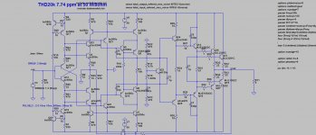
This is my best(up to now) CFA, with very benign hormonic distribution even at 20Khz.
THD20k is 7.74 ppm at 52W on 8 ohm load. Nex step, simplification.
BR Damir
THD20k is 7.74 ppm at 52W on 8 ohm load. Nex step, simplification.
BR Damir
Attachments
Last edited:
- Home
- Amplifiers
- Solid State
- CFA Topology Audio Amplifiers