I should have said : it is not difficult for masters.
There undoubtedly are some here.
As far as high maximal slew-rates are not related to the non linearities in the audio band and even well above, I wonder why to try to get impressive numbers for them.
I fear that those who claim that very fast amplifiers sound better would be completely upset if submitted to rigorous comparative blind tests.
I like 10:1 margin against slew rate limiting under worst case. For this reason, I like an amplifier to have enough slew rate to operate at full power at 200kHz without slew rate limiting. This corresponds to 50V/us for a 100W 8-ohm amplifier.
Cheers,
Bob
I like 10:1 margin against slew rate limiting under worst case. For this reason, I like an amplifier to have enough slew rate to operate at full power at 200kHz without slew rate limiting. This corresponds to 50V/us for a 100W 8-ohm amplifier.
These are certainly sufficient specifications to get excellent audio results and I think you demonstrated, that with some care, they can be obtained by VFAs.
Regards.
Hi Richard,
I respectfully disagree. I don't think we are here merely to design the very best possible CFA. We need a common-ground perspective on CFA vs VFA. That will help us converge on a better CFA using the advantages that we clearly see of the CFA (assuming there are some).
For me, selfishly, what I want to know is "why should I design/build a CFA"? I already know that I can build a very good VFA.
Bob
There is no disagreement on the outcome -- just proceedure. IMO we might consider need to get thru an output stage design and put together what we have at this point. We can change it later as SIM or tests show need or benifit etc. [ -- this is from my project experience and time-lines. If it matters.]
Otherwise, each takes his/her own way... as we see happen here over and over. So, let me attempt again to refocus this group by trying another approach -- the worlds best via the Internet (and not under NDA with employer or others) are here: Since I seem to have a longer history with CFA amps and it has not been explored as much as VFA let me offer my own feeble attempt at a real power amp data/measurments to shoot for with a CFA style amp not using very high gnfb. [both channels driven... lower levels - lower thd, of course] Simple design results - not nearly as complex as has been demonstrated here by others. No exotic and hard to get/expensive parts; FET output stage:
All THD+Noise. Production:
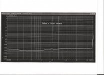

And at 1 dB below clipping -250W vs freq. Prototype:
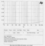
If we stay on track and 'git er dun' as a Phase 1 progress, then we can see more data and refinements and even better results in Phase 2.
[ -- the shown is from data of 10 years ago design.]
THx-RNMarsh
Last edited:
There is no disagreement on the outcome -- just proceedure. IMO we might consider need to get thru an output stage design and put together what we have at this point. We can change it later as SIM or tests show need or benifit etc. [ -- this is from my project experience and time-lines. If it matters.]
Otherwise, each takes his/her own way... as we see happen here over and over. So, let me attempt again to refocus this group by trying another approach -- the worlds best via the Internet (and not under NDA with employer or others) are here: Since I seem to have a longer history with CFA amps and it has not been explored as much as VFA let me offer my own feeble attempt at a real power amp data/measurments to shoot for with a CFA style amp not using very high gnfb. [both channels driven... lower levels - lower thd, of course] Simple design results - not nearly as complex as has been demonstrated here by others. No exotic and hard to get/expensive parts; FET output stage:
View attachment 372435
View attachment 372436
If we stay on track and 'git er dun' as a Phase 1 progress, then we can see more data and refinements and even better results in Phase 2.
[ -- the shown is from data of 10 years ago design.]
THx-RNMarsh
OK, lets settle on a Locathi T circuit Triple output stage using the OnSemi perforated emitter transistors. One output pair, 0.22R REs, and +/- 50V rails.
Cheers,
Bob
Show of hands? Or forever hold ur peace (at least for phase 1).
-RNM
[BTW- the measured - 'as-built' data is close to the A-P SYS One residual... so I dont have a clear, accurate idea of the real levels of THD+N or THD.... esp at lower output levels. Maybe the new 2722 or Shibasoku will help see far below the SYS One]
-RNM
[BTW- the measured - 'as-built' data is close to the A-P SYS One residual... so I dont have a clear, accurate idea of the real levels of THD+N or THD.... esp at lower output levels. Maybe the new 2722 or Shibasoku will help see far below the SYS One]
Last edited:
Comparing two reasonably straightforward reference designs (VFA and CFA) using the same transistor models, the same simulator, about the same level of complexity and about the same gain and phase margins, would probably help shed more light on the answer to this question. These reference designs need not be complex "hero" amplifiers, but should be good designs.
For the VFA, I'd suggest one with an LTP input stage loaded with a current mirror, followed by a 2-transistor single-ended VAS loaded with a quality current source, and completed with a Locanthi T-circuit Triple output stage. It would use conventional Miller compensation (no TPC or TMC for starters), would probably have ULGF somewhere in the range of 1-1.5MHz, and provide minimum gain and phase margins of 10dB and 60 degrees. I'd suggest the OnSemi perforated emitter output transistors with RE=0.22 ohms.
Including current sources, we'd probably be talking on the order of 16 transistors.
I'm going to put forward the circuit in my #499 post. The performance, slightly modified, in post #823 is still SOA and easily meets all of Bob's stability criteria.Show of hands? Or forever hold ur peace (at least for phase 1).
What it illustrates is that if you don't force arbitrary separation of IPS VAS OPS, you can get excellent performance with very simple and stone-age circuits.
If you want perfect IPS + perfect VAS + perfect OPS, the complexity of EACH of these 'perfect' stages is equal or greater than the whole of #499.
You are of course welcome to consider the whole #499 an OPS. Just drive with a CFA monolithic OPA and call the whole shebang a CFA amp 🙂
As I've said ad nauseum, the real worth of each stage isn't how perfect it is in itself, but if it interacts with other stages in a serendipitituous manner. (KC-P's OPS is an example of a 'perfect' OPS that is cr*p when connected to something else.)
A big part of this is whether it can use the Holy 'pure Cherry' compensation 😀
Last edited:
I was talking 60 dB at 20 kHz. You can get that with TPC. I agree that the output stage is the issue - that's why the absolute upper limit for ULGF for all my designs is 3 MHz.
This does nothing though to invalidate CFA as a useful topology for audio though.
This does nothing though to invalidate CFA as a useful topology for audio though.
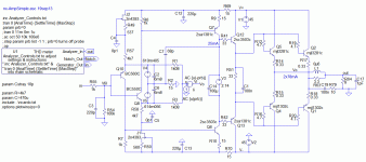
I've been doing sims of Bonsai's http://hifisonix.com/nx-amp/.
I like to have a starting point that is at least bears some resemblance to 'real life' ... in this case, Bonsai's measurements. It wasn't as straightforward as I expected. To get to my near 'real life' starting point, I had to
I like to have a starting point that is at least bears some resemblance to 'real life' ... in this case, Bonsai's measurements. It wasn't as straightforward as I expected. To get to my near 'real life' starting point, I had to
- replace his modes with Bob Cordell's including using BC550/560C for the input to get similar THD
- increase his R34/35 from 4k7 to 9k1. These set the IPS currents but the original value didn't allow his specified VAS 25mA current.
(Bonsai is currently looking at reducing VAS current by increasing R30/31 emitter resistors ... but that would drop the loop gain even further.) - I've also reduced his rail voltages from 50V to 45V for reasons that will become obvious later
Attachments
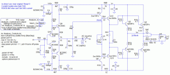
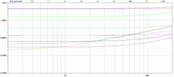
simple CFA input vs Diamond input
The evil reason for this work is cos I wanted to compare simple CFA input vs Diamond input 😱
The conversion attempts to run each stage at about the same current. Compensation etc is unchanged.
THD has dropped 3dB all round. It's actually 2 less devices. I could have kept the Zener supply to the i/ps but I really want more PSR in these CFA inputs.
Attachments
I'm going to put forward the circuit in my #499 post. The performance, slightly modified, in post #823 is still SOA and easily meets all of Bob's stability criteria.
What it illustrates is that if you don't force arbitrary separation of IPS VAS OPS, you can get excellent performance with very simple and stone-age circuits.
If you want perfect IPS + perfect VAS + perfect OPS, the complexity of EACH of these 'perfect' stages is equal or greater than the whole of #499.
You are of course welcome to consider the whole #499 an OPS. Just drive with a CFA monolithic OPA and call the whole shebang a CFA amp 🙂
As I've said ad nauseum, the real worth of each stage isn't how perfect it is in itself, but if it interacts with other stages in a serendipitituous manner. (KC-P's OPS is an example of a 'perfect' OPS that is cr*p when connected to something else.)
A big part of this is whether it can use the Holy 'pure Cherry' compensation 😀
Its the reason we stick with what we have developed so far.... Then make any necessary adjustmments/improvements for a more 'perfect' match.
Can we hear more on which is the better ops topology for this CFA --- so far CMA input and CConveyer and then OPS... and why a particular ops is better for this CFA topology chosen? ... some debate/lobbying is needed and then decide. WE have two very good suggestions from two very worthy sources to consider. What else is being put on the table for Phase 1 ??
The floor microphone is open.
-RNM
Last edited:
Richard, thanks for putting the sim up. Indeed, using the right models is critical, and especially so since the degeneration resistor values are low.
The alternative simple input stage you posted IMV has the clear disadvantage of two fat electrolytics and the IPS associated bias network - it's actually not simpler.
The advantage of the simple nx-Amp front end is that it is completely DC coupled - no caps and its extraordinarily stable once the initial offset has been dialed out. This kind of figures because the Vbe's all cancel, the collector currents are all equal and the Vce's are all equal.
Last edited:
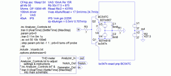
CFA input stages
Didn't really know what to expect and these results were certainly thought provoking. 😱
Decided to go against my own exhortations and investigate these 2 input stages on their own. I also wanted to replicate some Jurassic 'real life' THD work I'd done with the simple CFA input though this was not power amps but a very low noise application. 🙂
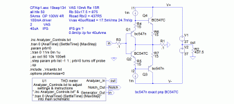
Loadsa trial test circuits later, I ended up with the 2 attached. You are welcome to dream up your own. Note the estimated output required based on 100W 4R, all hfe 50 & VAS 10mA current. I haven't allowed for the i/p 'load' resistors (R6/7 in nx-Amp & nx-AmpSimple) which would probably double the load.
... loadsa sims later .. FINDINGS
- Device matching is critical for Diamond. Tried all suitable devices including the LTspice ones, Gurus Wurcer & Cordell, most of those suggested in the Discrete Opamp Open Design thread
- best match were Cordell's bc550/560C.
- Both topologies have low THD which drops rapidly with level. Much better than LTP at similar currents
- Neither are likely to contribute THD to a complete amp even at very modest FB levels
- Diamond has a THD advantage over 'simple' but its unlikely to be achieved cos the matching required. I constructed an exact pnp complement to BC547C to check I wasn't doing something stupid
- Diamond needs emitter resistors to have even a semblance of match
- Diamond has a 3dB disadvantage in Gain. This fully explains the 3dB better distortion of nx-AmpSimple
- In most CFAs, 'simple input' is likely to have a small advantage in THD cos extra Loop Gain
- This may change if the rest of the amp's THD contribution drops by more than an order of magnitude 😀
- The 'flat THD profile' of CFA isn't inherent but probably cos the interface between i/p & VAS is via the i/p 'load' resistor (R6/7 in my nx-Amp models). ie its cos low Loop Gain at LF
- The disadvantage of 'simple' is a couple of large evil electrolytics but these are operated under optimal low stress conditions and unlikely to introduce THD
- From Bonsai's experience, Diamond doesn't have any DC offset advantage over 'simple'. Both need tweaking or a servo. LC's VSSA shows drift is not a problem
Attachments
Last edited:
Richard (Marsh),
I don't think there are any easy answers to the output stage distortion dilemma without incurring additional complexity.
I have shown a CFA sim design earlier that gets to the 5 ppm level at 20 kHz at full power and drops off rapidly after that. The OPS is indeed the limiting factor, but I don't think additional complexity to lower it further is warranted.
I'll finish off by suggesting a look at #825 and the slight mod in #1117
The comparison is with dadod's #942
I'm not sure going from my 6ppm to Damir's 5.6ppm is worth the extra complexity.
____________
BTW, I'm in no way attempting to dis either dadod or Bonsai. Both of them have done some very simple real life designs with excellent performance and hence have my greatest respect.
____________
What we need is an elegant (ie simple) way to interface a CFA i/p with a good VAS. (Current mirror on the LTP output is elegant) I don't think Damir's circuit is it 😀
If it has Holy Hooks for 'pure Cherry', this would solve the o/p THD too 🙂
Maybe double Rush cascodes but that's 4 extra devices
Until then, simple CFAs have an advantage over simple VFAs .. maybe down to 10ppm THD20k.
For lower THD, VFAs seem to have an advantage until we work this out. I don't think you'll see any advantage with Diamond i/p over 'simple' until we do.
But when we do, the supa CFA is likely to have a THD profile similar to a good VFA 😀
Last edited:
I was talking 60 dB at 20 kHz. You can get that with TPC. I agree that the output stage is the issue - that's why the absolute upper limit for ULGF for all my designs is 3 MHz.
This does nothing though to invalidate CFA as a useful topology for audio though.
3MHz is a pretty aggressive ULGF. More power to you if you can reliably achieve it with really good gain and phase margin over a wide range of conditions. I don't think I'd go as far out as 3MHz just to chase super-low THD.
There is no question that CFA is a useful topology for audio; the question is how much and what does it bring to the table as compared to VFA.
Cheers,
Bob
Harmonic Products vs IMD products
I scribbled it in our copy of the B&K 1902 manual and used scaling to match how it did this measurement. For a wideband device, there is exact correlation.
Could you ask a tame Mathematician to work this out again and publish it in your next edition? My single brain cell was still alive when I did this but its long gone senile. 😡
I don't think I allowed for feedback but this would still be useful.
____________________
BTW, this is an argument for Cherry's attitude that you should maximise FB in the audio range and let stuff above 20kHz go to Hell. He has a point though I'm not sure I want to go all the way down that road.
____________________
Surely that's worth more than a passing reference in your next edition?
At the present SOA, complex CFA lags behind complex VFA especially if you want 1 pp zillion THD but I'm hoping this thread will address that.
[deleted : 12 pgs on why simple stuff sounds better than complex stuff bla bla] 🙂
Bob, in da dim & distant past, I once worked out the equivalent value of each harmonic product and the corresponding IM product.This is exactly right, and what some people do not understand. Harmonic distortion is an indicator of nonlinearity. The results of nonlinearity that one hears, especially from nonlinearity at high frequencies, is more likely intermodulation products. That is why, in the best case, I prefer the 19+20kHz CCIF IM test. The same nonlinearities that give rise to harmonic distortion will also give rise to CCIF IM distortion. Nowadays CCIF IM is much more practical to measure than it once was because it generally requires a spectrum analyzer. That is now not a problem with PC-based instrumentation.
But as far as comparisons and benchmarks, THD20 is still more generally recognized as a common ground. I'm not sure there is a single-number measurement value for CCIF IM, as there is for THD20, but if there was it would not necessarily be the same value and comparable to the corresponding number for THD20 for the same amplifier.
The effect of negative feedback as a function of frequency can also create an important difference between the THD20 and CCIF IM distortion measures. Second and third-order nonlinearities create harmonics at 40kHz and 60kHz, where the amount of negative feedback is almost inevitably lower and its distortion-reducing capability smaller.
On the other hand, second and third order nonlinearities create in-band IM distortion components at 1kHz and 18kHz, respectively in the CCIF IM test (I'm ignoring IM products that are created above 20kHz). There is often vastly more negative feedback at 1kHz, and usually more negative feedback at 18kHz than at 60kHz. So usually the negative feedback will have a larger distortion-reducing effect on the IM components of the CCIF IM test than on the harmonic components of the THD20 test.
I scribbled it in our copy of the B&K 1902 manual and used scaling to match how it did this measurement. For a wideband device, there is exact correlation.
Could you ask a tame Mathematician to work this out again and publish it in your next edition? My single brain cell was still alive when I did this but its long gone senile. 😡
I don't think I allowed for feedback but this would still be useful.
____________________
BTW, this is an argument for Cherry's attitude that you should maximise FB in the audio range and let stuff above 20kHz go to Hell. He has a point though I'm not sure I want to go all the way down that road.
____________________
It brings better performance for simple stuff.Bob Cordell said:There is no question that CFA is a useful topology for audio; the question is how much and what does it bring to the table as compared to VFA.
Surely that's worth more than a passing reference in your next edition?
At the present SOA, complex CFA lags behind complex VFA especially if you want 1 pp zillion THD but I'm hoping this thread will address that.
[deleted : 12 pgs on why simple stuff sounds better than complex stuff bla bla] 🙂
Last edited:
The large electro cap do not contribute to lowering distortion. Even if they produce zero distortion themselves... they do not reduce the circuits distortion. They have to go for that reason alone. reasons not related to the distortion or improving any other parameter (besides dc offset) would be reliability, cost, size/real-estate, lmited life compared to the other parts. They have to go.
Rgrlee --- to what degree is matching needed and for what kind of change in thd? matching itself isnt a disqualifier unless it is unreasonably tight.
Thx-RNMarsh
Rgrlee --- to what degree is matching needed and for what kind of change in thd? matching itself isnt a disqualifier unless it is unreasonably tight.
Thx-RNMarsh
Last edited:
Richard (Marsh),
I don't think there are any easy answers to the output stage distortion dilemma without incurring additional complexity.
I have shown a CFA sim design earlier that gets to the 5 ppm level at 20 kHz at full power and drops off rapidly after that. The OPS is indeed the limiting factor, but I don't think additional complexity to lower it further is warranted.
OK, sounds like the OPS is dominating distortion, as expected. If you take that same output stage and use it in a VFA with about the same complexity and devices and stability, can you get to 5ppm?
Cheers,
Bob
I think its unreasonable but that's personal.Rgrlee --- to what degree is matching needed and for what kind of change in thd? matching itself isnt a disqualifier unless it is unreasonably tight.
More important is that both topologies are excellent for THD and way better than needed ... until we can improve the CFA IPS/VAS interface.
Should be able to -in practice. Looking for a number here .. for tolerance in matching. can you run your sim and tell us.
Yes the output stage needs to be interfaced with the CM operation as best we can and see what happens.
Ok We got the diamond if matching isnt rediculous (should not be with biploars) and simple cf stage if it is.... a le Bonsia.
The second stage - which is best to interface with this ips?
then which ops is best for that gain stage?
We are almost there.... leaving the final ops to debate.
What will also fall out remains the compensation method(s) and which is realistically usable from a build view (rather than purely sim). I have found very little needs to be done with my amps and the methods are very stable without affecting thd as much as VFA.
Then we will be going into Phase 3-- my favorite part -- further simplifying thru cancellations.
THX-RNMarsh
Last edited:
- Home
- Amplifiers
- Solid State
- CFA Topology Audio Amplifiers
