Just pile on the loop gain. When you can do it with 60dB of loop gain, you have made progress.
It's impossible to get 60dB of loop gain at HF ( to account for 20KHz thd reduction) in any possible implementation of a power amplifier (discrete or IC) if it is to also provide any decent stability margins. The output stage bandwidth won't allow that.
But this is good start to get it in real life too.
Not much, at those levels.
yes it does look like TPC can get you there
as seen in my earlier post: http://www.diyaudio.com/forums/solid-state/240712-cfa-topology-audio-amplifiers-73.html#post3615032
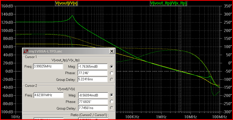
77 degrees phase margin, >15 dB gain, margin, with ~65 dB loop gain @ 20kHz
the insight that the output stage in audio power amps is limiting allowable stable feedback leads me to my "less than impressed" with CFA position - its just another input error amp&gain stage choice that can only be tuned up to the slow output stage's limit so it just can't really achieve anything startlingly "better" than known "VFA" front end
as seen in my earlier post: http://www.diyaudio.com/forums/solid-state/240712-cfa-topology-audio-amplifiers-73.html#post3615032
77 degrees phase margin, >15 dB gain, margin, with ~65 dB loop gain @ 20kHz
the insight that the output stage in audio power amps is limiting allowable stable feedback leads me to my "less than impressed" with CFA position - its just another input error amp&gain stage choice that can only be tuned up to the slow output stage's limit so it just can't really achieve anything startlingly "better" than known "VFA" front end
Last edited:
Not even with a two pole compensation method. 60dB @60KHz (to fight the crossover distortions which are usually dominant in any class AB output stage) would require a theoretical ULGF of about 6MHz (40dB drop at 40dB/dec, then 20dB drop at 20dB/dec to bring the phase back.
Cherry's NDFL would allow 60dB of loop gain, but we are already deep in unchartered waters from a practical perspective.
there's no evidence that
and another point some seem to ignore is that IMD products, even those "created" by higher frequency errors - are reduced by Global loop gain at the product frequency - not by the "source" frequencies
this means that the example 19+20 kHz 2nd order difference frequency at 1 kHz is reduced by the ~120 dB loop gain at 1 kHz in my sim
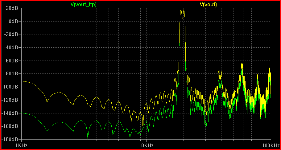
yes there isn't a big advantage at 60 kHz, but where we know we can hear, < 20 kHz, there is a big improvement with high Global loop gain
it doesn't particularly matter whether you achieve the high loop gain with VFA or CFA - but someone has to show the CFA with improved loop gain - give up the flawed "flat, high open loop bandwidth" idea as a desired feature
has any real meaning/consequence in the example designs in play - all are using 100+ mA output device bias60dB @60KHz (to fight the crossover distortions which are usually dominant in any class AB output stage)
and another point some seem to ignore is that IMD products, even those "created" by higher frequency errors - are reduced by Global loop gain at the product frequency - not by the "source" frequencies
this means that the example 19+20 kHz 2nd order difference frequency at 1 kHz is reduced by the ~120 dB loop gain at 1 kHz in my sim
yes there isn't a big advantage at 60 kHz, but where we know we can hear, < 20 kHz, there is a big improvement with high Global loop gain
it doesn't particularly matter whether you achieve the high loop gain with VFA or CFA - but someone has to show the CFA with improved loop gain - give up the flawed "flat, high open loop bandwidth" idea as a desired feature
Last edited:
as seen in my earlier post: http://www.diyaudio.com/forums/solid-state/240712-cfa-topology-audio-amplifiers-73.html#post3615032
77 degrees phase margin, >15 dB gain, margin, with ~65 dB loop gain @ 20kHz
the insight that the output stage in audio power amps is limiting allowable stable feedback leads me to my "less than impressed" with CFA position - its just another input error amp&gain stage choice that can only be tuned up to the slow output stage's limit so it just can't really achieve anything startlingly "better" than known "VFA" front end
Loop gain @20KHz helps lowering the 10KHz 2nd harmonic, etc... If we choose the performance metric THD20, then what matters is the loop gain @60KHz which helps fighting the 20KHz crossover distortions.
Otherwise, 60dB loop gain @20KHz is indeed possible with a two pole compensation method. Your example is perfect, now check how much do you have to push the ULGF to get 60dB @60KHz.
Originally Posted by Bcarso
some acclaimed amplifiers are astonishingly noisy.
In some circumstances, a bit of additional noise can unveil details not perceived otherwise. The effect is well known in photography, it also occurs with sound :
"Can noise improve your hearing ?"
Electronics World + Wireless World, December 1993, p976.
The article quotes :
- Franck Moss and colleagues from the University of Missouri
- Nature vol 365, No 6444
Yes, I've long been aware of, and even recently posted a link to the wiki on Stochastic Resonance.
The level at which it may be operant will of course vary depending on other system characteristics, particularly loudspeaker sensitivities. My suspicion is that some of the amps I have in mind are well in excess of the optimal amount, but YMMV.
Otherwise, 60dB loop gain @20KHz is indeed possible with a two pole compensation method. Your example is perfect, now check how much do you have to push the ULGF to get 60dB @60KHz.
This is realy absurd, are we making ultrasonic amplifier? THD20k is just indication how low distortion is not that we can hear 20kHz or 40kHz and 60kHz.
I do show a technique if you just want probably meaningless improvement in THD 20K
is 30 dB enough? Black's earlier invention of Feedforward correction, aka "current dumping"
http://www.diyaudio.com/forums/soli...in-composite-op-amp-circuits.html#post2415805
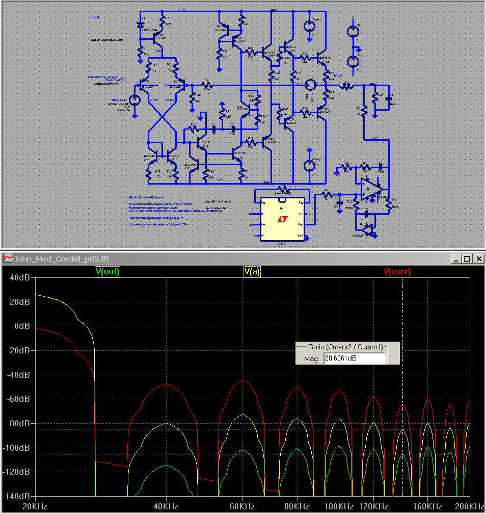
and note that the error feedforward amp is CFA - in the configuartion that does offer some clear advantages - a monolithic op amp with output Q of similar GHz ft as the input/mirror/"gain" stages
is 30 dB enough? Black's earlier invention of Feedforward correction, aka "current dumping"
http://www.diyaudio.com/forums/soli...in-composite-op-amp-circuits.html#post2415805
and note that the error feedforward amp is CFA - in the configuartion that does offer some clear advantages - a monolithic op amp with output Q of similar GHz ft as the input/mirror/"gain" stages
Last edited:
as seen in my earlier post: http://www.diyaudio.com/forums/solid-state/240712-cfa-topology-audio-amplifiers-73.html#post3615032
77 degrees phase margin, >15 dB gain, margin, with ~65 dB loop gain @ 20kHz
the insight that the output stage in audio power amps is limiting allowable stable feedback leads me to my "less than impressed" with CFA position - its just another input error amp&gain stage choice that can only be tuned up to the slow output stage's limit so it just can't really achieve anything startlingly "better" than known "VFA" front end
jcx,
This is my gut feeling as well, at the end of the day.
Comparing two reasonably straightforward reference designs (VFA and CFA) using the same transistor models, the same simulator, about the same level of complexity and about the same gain and phase margins, would probably help shed more light on the answer to this question. These reference designs need not be complex "hero" amplifiers, but should be good designs.
For the VFA, I'd suggest one with an LTP input stage loaded with a current mirror, followed by a 2-transistor single-ended VAS loaded with a quality current source, and completed with a Locanthi T-circuit Triple output stage. It would use conventional Miller compensation (no TPC or TMC for starters), would probably have ULGF somewhere in the range of 1-1.5MHz, and provide minimum gain and phase margins of 10dB and 60 degrees. I'd suggest the OnSemi perforated emitter output transistors with RE=0.22 ohms.
Including current sources, we'd probably be talking on the order of 16 transistors.
Cheers,
Bob Cordell
Cherry's NDFL would allow 60dB of loop gain, but we are already deep in unchartered waters from a practical perspective.
Actualy his textbook exemple using a four stages topology
to implement three nested FBL has been used in a commercial
amplifier , though i cant readily point how much NFB
ratio was extracted at higher frequencies but in simulation
of said design numbers are extremely low for distorsions
of all kind.
Stay focused -
Comparisons of circuits and topologies or reference designs are easy to do in SIM.
We still need a really good output stage for the CFA. Then pull all the progress to date together as one. see what that does.
Without elaboration -- In practice however, the issue of low distortion, IM, SR, etc in one will be much easier to impliment and get good results than the other. Especially in practice. The problem area in my experience will always be the stability vs HF distortion. This might be the only area which the CFA will show its promise.
Focus.... comparisons is not what this is about ... we started down that path in the beginning and it is always there to bring up over and over. We want to design a CFA here... only. Then see what has fallen out of that development. Maybe build it and measure it and listen.
Thx-RNMarsh
Last edited:
This is realy absurd, are we making ultrasonic amplifier? THD20k is just indication how low distortion is not that we can hear 20kHz or 40kHz and 60kHz.
You are not debating the facts, but the distortion metric. I may or may not agree about THD20 as the best distortion metric, but this seem to be the common platform here.
I might be wrong, but the strongest promoter of THD20 with 200KHz (or even 600KHz) bandwidth seem to be Mr. Cordell, so you may want to re-direct your comments to him.
Actualy his textbook exemple using a four stages topology
to implement three nested FBL has been used in a commercial
amplifier , though i cant readily point how much NFB
ratio was extracted at higher frequencies but in simulation
of said design numbers are extremely low for distorsions
of all kind.
Actually syn08's PGP amp uses NDFL in the front end and reached under 1ppm THD20 @100W/8ohm. However, the PGP amplifier is what I would call a pathological design case of sheer complexity, primary intended to show off some unusual numbers. I would swap a PGP amp any day with an amplifier that would deliver clean 200W into 8ohm and 400W into 4 ohm with 10-20ppm distortions (like his YAP amp, or one of Bonsai's designs).
Black's earlier invention of Feedforward correction, aka "current dumping"
Feedforward error correction like the "current dumping" scheme is a completely different kettle of fish, which is to me largely outside this thread's topic.
I would be highly interested in a topic that would rigorously analyze, characterize and optimize such a topology. The Quad 405 design would be a good start.
Richard, now i believe we can fight endless with sims with no results if each step is not subjectively validated with real listening.
On my opinion, what's make the difference with CFAs are its defects. What you called brilliantly "expansive". Means VFA underline transients, little details in music. In a way, compensate their losses in recording processes.
Sometimes, even a little overshoot brings advantages, and little nice distortion can add subjective presence ;-)
We yet know that it is possible to build very simple CFAs with noise and distortions well under the level disagreeable to our ears.
Each attempt i had done in my life to get better numbers, using complicated assemblies for the input, VAS, and output stage in a feedback amplifier brought to the same result you lightened: instability, painful and sensitive tuning. Or a boring result, on the listening side, because what we have win on one point was at the detriment of an other aspect.
It is like TPC etc... it looks like desperate attempts to tune the phases at the limit. Acrobatic.
I tried those days to sim several error corrections topologies for output stage in CFAs.
I will lurk, passionated, if experienced designers, here, can do better than my total failure: a formula one transformed in a limousine.
Yet with 3 single simple stages, 3 poles in the loop with very close cutoff frequencies we don't want to reduce, Sir Nyquist is watching-us, amused, betting and laughing with his neighbor, sir Murphy 🙂
Last edited:
This is realy absurd, are we making ultrasonic amplifier? THD20k is just indication how low distortion is not that we can hear 20kHz or 40kHz and 60kHz.
This is exactly right, and what some people do not understand. Harmonic distortion is an indicator of nonlinearity. The results of nonlinearity that one hears, especially from nonlinearity at high frequencies, is more likely intermodulation products. That is why, in the best case, I prefer the 19+20kHz CCIF IM test. The same nonlinearities that give rise to harmonic distortion will also give rise to CCIF IM distortion. Nowadays CCIF IM is much more practical to measure than it once was because it generally requires a spectrum analyzer. That is now not a problem with PC-based instrumentation.
But as far as comparisons and benchmarks, THD20 is still more generally recognized as a common ground. I'm not sure there is a single-number measurement value for CCIF IM, as there is for THD20, but if there was it would not necessarily be the same value and comparable to the corresponding number for THD20 for the same amplifier.
The effect of negative feedback as a function of frequency can also create an important difference between the THD20 and CCIF IM distortion measures. Second and third-order nonlinearities create harmonics at 40kHz and 60kHz, where the amount of negative feedback is almost inevitably lower and its distortion-reducing capability smaller.
On the other hand, second and third order nonlinearities create in-band IM distortion components at 1kHz and 18kHz, respectively in the CCIF IM test (I'm ignoring IM products that are created above 20kHz). There is often vastly more negative feedback at 1kHz, and usually more negative feedback at 18kHz than at 60kHz. So usually the negative feedback will have a larger distortion-reducing effect on the IM components of the CCIF IM test than on the harmonic components of the THD20 test.
Cheers,
Bob
Comparisons of circuits and topologies or reference designs are easy to do in SIM.
We still need a really good output stage for the CFA. Then pull all the progress to date together as one. see what that does.
Without elaboration -- In practice however, the issue of low distortion, IM, SR, etc in one will be much easier to impliment and get good results than the other. Especially in practice. The problem area in my experience will always be the stability vs HF distortion. This might be the only area which the CFA will show its promise.
Focus.... comparisons is not what this is about ... we started down that path in the beginning and it is always there to bring up over and over. We want to design a CFA here... only. Then see what has fallen out of that development. Maybe build it and measure it and listen.
Thx-RNMarsh
Hi Richard,
I respectfully disagree. I don't think we are here merely to design the very best possible CFA. We need a common-ground perspective on CFA vs VFA. That will help us converge on a better CFA using the advantages that we clearly see of the CFA (assuming there are some).
For me, selfishly, what I want to know is "why should I design/build a CFA"? I already know that I can build a very good VFA.
I have seen numerous arguments here that could have been readily answered by simulation rather than by speculation. That is a very big value-added for simulation. At the same time, the practicalities that come into play when the amplifier is actually built are also very important. Once again, if two comparable reference designs were built, which one would do better in the real world?
Cheers,
Bob
It is not that difficult to get sub-ppm distortion together with other high specifications for slew-rate or noise. Let's not forget PSRR...
I should have said : it is not difficult for masters.
There undoubtedly are some here.
As far as high maximal slew-rates are not related to the non linearities in the audio band and even well above, I wonder why to try to get impressive numbers for them.
I fear that those who claim that very fast amplifiers sound better would be completely upset if submitted to rigorous comparative blind tests.
- Home
- Amplifiers
- Solid State
- CFA Topology Audio Amplifiers