Only C6, C4, R1, C2, C3 and C5 belong to signal ground (GND1).
Ok...
All supply coupling caps should be connected to Power Ground, not Signal Ground.
Ok i hear that...look under first step MT200-50 version
Attachments
TR1 (1K) and R6 (680) should be in series. If they are parallel, there is possibility to equalize voltage of the base and emitter of transistor Q6. You can decrease R6 to let say 100R and keep value of TR1.
Last edited:
Ok i hear that...look under first step MT200-50 version
It's better. Just connect 22k to Power GND, and that's it. You can put 22k between 2200 and 470uF.
Idefixes
You are the hard working man!!
But BG1 is not the lastest amplifier 😛
BG2 Mini (has been released few weeks ago), and now just passed first tests the BG3 - diamond input + TEF amplifier (first impression is really nice).
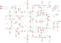
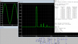
Simulation of BG3 bellow (measurements later on), after I will finish it i will release schematic.
You are the hard working man!!
But BG1 is not the lastest amplifier 😛
BG2 Mini (has been released few weeks ago), and now just passed first tests the BG3 - diamond input + TEF amplifier (first impression is really nice).
Simulation of BG3 bellow (measurements later on), after I will finish it i will release schematic.
Attachments
Idefixes
You are the hard working man!!
But BG1 is not the lastest amplifier 😛
BG2 Mini (has been released few weeks ago), and now just passed first tests the BG3 - diamond input + TEF amplifier (first impression is really nice).
Simulation of BG3 bellow (measurements later on), after I will finish it i will release schematic.
Hi Borys,
any differences in sound between BG1 and BG2?
Marc
TR1 (1K) and R6 (680) should be in series. If they are parallel, there is possibility to equalize voltage of the base and emitter of transistor Q6. You can decrease R6 to let say 100R and keep value of TR1.
That is correct.
The original idea was after you set up the offset replace the trimmer with resistor if you like.
In one word no need for both.
Greetings G
TR1 (1K) and R6 (680) should be in series. If they are parallel, there is possibility to equalize voltage of the base and emitter of transistor Q6. You can decrease R6 to let say 100R and keep value of TR1.
Yes but, before power up the amp You must set trimer/resistor combo to 330r, after that you will need only couple of turns to set the offset (I think is safe enough)
Second trimmer (bias) set at max value before powering the amp.
Idefixes
BG2 Mini is for someone who was playing with some lm3xxx or tdaxxxx chips etc and is going to build firs decent amp.
Amp is very simple (like from a book), it is based on sansui from 1974.
It has very detailed sound (warm character) and really good base response.
I am not good in therms of sound description - anyway is really big surprise of small simple amp, worth to build it.
I will see how the bg3 will go on.
Ok i continue to play with BJT output device as i have in stock enough. I will see what BG3 i have 2 240/9240 couple...
I really enjoy day to day BG1-BJT...and after two week i continue to surprise me even i hear music in back ground when i am doing something different...
Marc
Hi Marc, Borys,Ok i continue to play with BJT output device as i have in stock enough. I will see what BG3 i have 2 240/9240 couple...
I really enjoy day to day BG1-BJT...and after two week i continue to surprise me even i hear music in back ground when i am doing something different...
Marc
I was referred to this thread via VSSA GB. Got the modules from LC and caught the VSSA bug.
I'm planning to build the BG1-BJT with the following transistors that I have: BC550C/560C, BD139-16STU/140-16STU, MJ15024/15025. I only have fix regulated +/-24V supplies. With only these transistors initially and substituting the BD139-16/140-16 for the 2SC5171 and 2SA1930, MJ15024/15025 for C5200 and A1943, do I have to make any changes on the resistors and/or capacitors values?
Your recommendations are highly appreciated.
Thanks,
WP
Hi Marc, Borys,
I was referred to this thread via VSSA GB. Got the modules from LC and caught the VSSA bug.
I'm planning to build the BG1-BJT with the following transistors that I have: BC550C/560C, BD139-16STU/140-16STU, MJ15024/15025. I only have fix regulated +/-24V supplies. With only these transistors initially and substituting the BD139-16/140-16 for the 2SC5171 and 2SA1930, MJ15024/15025 for C5200 and A1943, do I have to make any changes on the resistors and/or capacitors values?
Your recommendations are highly appreciated.
Thanks,
WP
Just solder them on the board should be fine. BD139-16/140-16 they are doing great job in that ciruit, they have high hfe - above average in this type of transistors.
Hi Marc,Just solder them on the board should be fine. BD139-16/140-16 they are doing great job in that ciruit, they have high hfe - above average in this type of transistors.
Ok then.will prep the parts and boards.
Thanks,
WP
Hi Marc, Borys,
I was referred to this thread via VSSA GB. Got the modules from LC and caught the VSSA bug.
I'm planning to build the BG1-BJT with the following transistors that I have: BC550C/560C, BD139-16STU/140-16STU, MJ15024/15025. I only have fix regulated +/-24V supplies. With only these transistors initially and substituting the BD139-16/140-16 for the 2SC5171 and 2SA1930, MJ15024/15025 for C5200 and A1943, do I have to make any changes on the resistors and/or capacitors values?
Your recommendations are highly appreciated.
Thanks,
WP
MJ15024/15025 seem to be TO3 like metal case package....that means you need adapt a board...
Marc
Hi Borys,
Could you provide a schematic based on BG2 with mod in bias area for 2sk1530/2SJ201 use?
Marc
Could you provide a schematic based on BG2 with mod in bias area for 2sk1530/2SJ201 use?
Marc
Hi Borys,
Could you provide a schematic based on BG2 with mod in bias area for 2sk1530/2SJ201 use?
Marc
I will draw tomorrow evening (but I think You mean BG1 with Toshibas cause BG2 mini is VFA simple amp).
In bias area You do not have to change anything, in case You can not get mosfets polarized you can replace 560R (lower one) in biasing circuit with 100R.
In my case mosfet toshibas are from group O and I have to get approx 4V between gates to get 100mA o/p bias.
For 2sj201/2sk1530 I would keep BJT transistor in bias servo, bias is approx 30% overcompensated.
Regards
Last edited:
I will draw tomorrow evening (but I think You mean BG1 with Toshibas cause BG2 mini is VFA simple amp).
In bias area You do not have to change anything, in case You can not get mosfets polarized you can replace 560R (lower one) in biasing circuit with 100R.
In my case mosfet toshibas are from group O and I have to get approx 4V between gates to get 100mA o/p bias.
For 2sj201/2sk1530 I would keep BJT transistor in bias servo, bias is approx 30% overcompensated.
Regards
No Borys i meant BG2-Hexfet...Without 2sc4793/2sa1837.... I will look at my holliday return in 10 days.
Marc
Last edited:
Nobody doing any further tests, build etc?
Very slow here for some reason last 2 weeks or so.
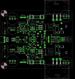
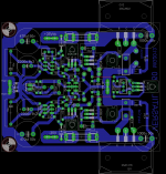
These circuit , these topology deserve to be build. Borys and Marc made it available to us a great amplifier and layout for PC boards
Cheers G
Very slow here for some reason last 2 weeks or so.
These circuit , these topology deserve to be build. Borys and Marc made it available to us a great amplifier and layout for PC boards
Cheers G
Last edited:
Nobody doing any further tests, build etc?
Very slow here for some reason last 2 weeks or so.
These circuit , these topology deserve to be build. Borys and Marc made it available to us a great amplifier and layout for PC boards
Cheers G
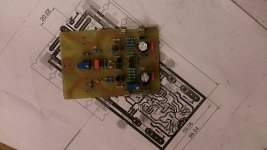
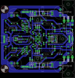
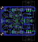
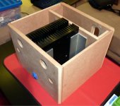
During my holiday i take my computer with me and continue to work on versatil version. Next week i will order some more epoxy to eatch Versatil 50 (one paire output) with MJL4281/4302 in test, Vesatil 100-3P (2 pair output) with MJW3281/1302 and BG2 Hexfet with one pair IRFP240/9140. Today i cut some MDF for Versatil 50 enclosure.
Attachments

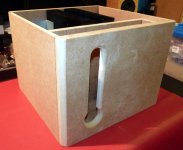
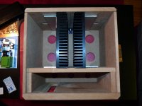
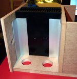
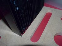
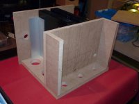
Today, i finished the cutting and routing job except top cover (i need to buy one more MDF pieces) on Versatil enclosure. The front compartiment will hold the 2 trafo and soft-start. I routelarge hole in the bottom plate to have good air circulation on heatsink.
Next step will be some gluing and than two layer epoxy resin and go for glossy black finish.
Next step will be some gluing and than two layer epoxy resin and go for glossy black finish.
Attachments
Last edited:
- Home
- Amplifiers
- Solid State
- FET-hex explendit amplifier