Simple question: maximum tanδ as specified in electolytic capacitor datasheets, refers to the worst case scenario, that is the capacitor is near the end of his usable life or something like that?
I mean, what value of ESR should we expect? The maximum impedance at 100kHz or so, or the ESR that can be calculated according to the maximum tanδ?
I find the first supposition to be more rational, but I really have no idea.
I mean, what value of ESR should we expect? The maximum impedance at 100kHz or so, or the ESR that can be calculated according to the maximum tanδ?
I find the first supposition to be more rational, but I really have no idea.
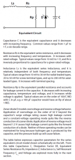
I've copied part of a Cornell Dubilier application guide below. Notice that "equivalent series resistance decreases with increasing frequency".
Dissipation Factor (tanδ) suggests the same thing: ESR = tanδ / (2πfC).
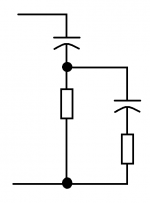
Thus ESR is not constant, and cannot be accurately modeled at all frequencies by a single resistor. Perhaps we can increase accuracy by including more than one resistor in our model of a real capacitor? Perhaps a two-resistor model as shown in the attachment, will give better results. The first resistor models ESR at 120Hz, and the (first resistor in parallel with the second resistor) models ESR at 100 kHz.
This idea may be straightforwardly extended, to prepare capacitor models employing three or more resistors. These can better fit the measured ESR vs frequency data of real capacitors.
Dissipation Factor (tanδ) suggests the same thing: ESR = tanδ / (2πfC).
Thus ESR is not constant, and cannot be accurately modeled at all frequencies by a single resistor. Perhaps we can increase accuracy by including more than one resistor in our model of a real capacitor? Perhaps a two-resistor model as shown in the attachment, will give better results. The first resistor models ESR at 120Hz, and the (first resistor in parallel with the second resistor) models ESR at 100 kHz.
This idea may be straightforwardly extended, to prepare capacitor models employing three or more resistors. These can better fit the measured ESR vs frequency data of real capacitors.
Attachments
Thanks for the answer! This is what I had also read to estimate a value for Ls. 🙂
So yes, it follows from the equation that ESR decreases with frequency. Notably, I have been thinking about all these after a comment of yours, reminding that capacitors are not ideal etc. So I wanted to safely estimate the HF suppresion of an R-C filter based on models that add ESR etc.
Therefore, it goes without saying that modelling everything with an ESR of some milliohms vs half an ohm or what, is extremely different. Maybe I will just use the maximum ESR for low frequencies, and estimate a value to include for HF - not zero. All this easies my efforts - good to know I can get rid of big ESR when in need of serious HF attenuation. 😛
I mentioned 100kHz or so, because I have sometimes seen curves indicating the capacitor impedance vs frequency, and I remember (of course I can be mistaken) graphs showing a minimum value around such frequencies. My guess is that indeed, there is a characteristic frequency for each capacitor that Ls cancels out with C - the capacitor then could have purely ohmic properties.
So I thought why not take the ESR measured while reaching that frequency, and use it in our model for all greater frequencies? I believe this would bring our HF suppresion simulations on the safe side. Apart from the fact of cource that should ESR really become zero for high frequencies, then this approach could include some damping that does not exist in real life for other frequencies that could be resonant ones - a dangerous thing. Still, it could hardly matter, provided one ensures that damping factors (series resistors, winding resistance etc) are present in reality.
Last edited:
About the construction of the circuit boards: two options.
"Point to point" using perforated boards, or order pcb's. I have designed a basic plan in Sprint-Layout, which I will post when it is finished.
The cheap one is point to point, I think it is more ideal in terms of track resistance, but is the tough one as far as time is concerned (I don't really mind about that). The expensive but easy to build is the pcb option.
Which one do you think is the best to use? Please elaborate on why you would choose that. Possible arguments could be cost, better layout leading to better performance, long-term reliability, easiness to build etc. Any opinion is welcome! 🙂
About the construction of the circuit boards: two options.
There is a third option that is likely the most common with guitar amp builders. It is called turret board construction. It is very strong, useful for those guitarist who hault their tube amps in the back up a van and load them up and down stairways and otherwise physically abuse their equipment. This construction was used for high end military gear up to about the second world war.
Here is a very good photo essay on how to build and amp that will last for a long time and be easy to service. I always use this method of construction, even for stereo HiFi gear. Although this builder makes nicer looking stuff then I do.
Allusion Ampworks Model X-1 Amplifier
Turrets are pressed into 1/8th inch fiberglass board. I can be made with hand tools in about an hour. I do layouts that mirror the schematic to make service years later easy. Everything is all square and neat like the dawning.
Techically this is better then a PCB. I use coaxial cables in the signal path and #12 solid wire for grounds. You can't do that in a PCB.
A variation of the turrect board is the eyelet board, tin platted brass eyelets are used in place of turrets. The eyelets are easier to find and cheaper. Here is a video of a factory in California where they are buillding tube amplifier by hand using eyelet boards
Fender Factory Tour: How to Build a Handwired Amp - YouTube
Finally here is a tube reverb unit I made using turret board. Some of the tubes are in shields only one is exposed glass and some of the transformers and the spring reverb pan are hidden on the other side of the chassis. Th solid maple enclosure is "way strong" and should last forever.
https://www.dropbox.com/s/nes72pnq0wsbbeg/guts%20angle%20view.jpg
But HiFi builders typically are happy with an expose metal chassis with exposed tubes. But NO COMPANY in the tube era would ever sell you an amp like that. Even in the 1950's it was unacceptable to not cover the tubes and have an insulated box.
We should try for high quality build, make it "furnature grade" rather then a lab experiment grade look.
Very nice - "turret" board methods.
I last saw this in production-equipment dating to the 1940s. Military communications equipment before the invention of the printed circuit board. Phenolic-cotton boards were drilled, and the turrets (solder-posts as they were called) were actually individually screwed into the board. Military overkill, I guess. Point is, that the same devices powered on and actually worked in the late 1980s, some 45 to 50 years after manufacture. A few electrolytics popped eventually, but with replacement, the shortwave receivers were just as good as when new.
Thanks!
GoatGuy
Many thanks for the answer!
I am well aware of the third option ChrisA! It is how I am planning to build my guitar amp. You see, it shall be a Hiwatt clone, and these amps were exclusively made with turret boards. I really love this technique!
But I did not include that in my post, since I feel that for small components (and radial ones) it is not that easy to implement in small scale - meaning that for each power supply, I would not want to exceed something like 3cm x 10cm for each board. 12 boards are needed. 🙂
I will consider your proposal either way! Maybe I just judge this too fast.
About the 100n bypass capacitor at the LM317 input, I have seen that often a disc capacitor is proposed.
Actually, isn't a low esr capacitor required here? I was thinking about Panasonic ECQ-V.
Actually, isn't a low esr capacitor required here? I was thinking about Panasonic ECQ-V.
http://www.stalker-lab.ru/forum/showthread.php?t=1177
.
Very good scheme (curcuit).
But in Russian.
.
.
Very good scheme (curcuit).
But in Russian.
.
???????????? ??????????? ???????? ??????? ? ??????? ??????????? ??????? ?????? - ????? STALKER-Lab
.
Very good scheme (curcuit).
But in Russian.
.
Thanks for the prompt, but I can't see any pictures, not being a member! 🙁
I will eventually use a capacitance multiplier (BD139), and then the LM317 stage. Seems a quite compact and good implementation to me. 🙂
I have decided to proceed the LM317 with a capacitance multiplier. I will also include a series resistor for further noise rejection, 1-2 ohms on experimentation.
There are two possible configurations:
(1) Bridge - C - R - capacitance multiplier - LM317
(2) Bridge - R - C - capacitance multiplier - LM317
I think the advantages of each are:
(1) Slightly lower voltage drop since R does not see the heavy ripple current of the reservoir, and it can be a very low wattage type - peak power will not exceed 100-200mW even at start-up.
(2) The R before the cap helps a bit as a soft-start element, which is good, but peak power here will be quite high even for a brief moment during start-up. So for long-term reliability, a higher wattage component should be used. Here I must adress a question - how many times can the working wattage be exceeded (for a brief period, of course) before the component becomes unreliable? Is there any rule of thumb?
Would you go with (1) or (2)? 🙂
Resistors have datasheets. These datasheets discuss average power and peak power; it is expected and allowed that {v(t) x i(t)} sometimes exceeds the rated "maximum" power. Check the datasheet.
Self's APADH discusses series resistors as soft start inrush current limiters; he gives guidelines for wattage selection based on his experience with reliable, working, commercial products. You might start with his recommendations, and then add another extra margin-of-safety, however much you need to make you feel comfortable.
I find that, in general, a resistor rated for "W" watts of power dissipation, starts to become "hot" to the touch, when its average power exceeds (W/3) watts. A 25 watt resistor (like THIS one) is hot to the touch, when dissipating 8 watts.
That metal encased resistor has mountings to fit a heatsink.............I find that, in general, a resistor rated for "W" watts of power dissipation, starts to become "hot" to the touch, when its average power exceeds (W/3) watts. A 25 watt resistor (like THIS one) is hot to the touch, when dissipating 8 watts.
It can only be a 25W resistor if a suitable heatsink is fitted.
Now when you fit a heatsink with a 100000C/W rating, what is the resistor power rating?
Now apply your 1/3rd rule. What temperature is the resistor casing running at, when properly implemented?
BTW,
your 1/3rd rule is good as a guide for resistor temperatures in the long term. I use similar myself.
But you MUST look at the actual resistor dissipation capabilities to be able to knowingly apply any such rule.
The problem is I am not sure I can get specific information on the limits of the resistors I will buy - going down the store to buy a cheap 5W resistor, I am not sure I will get any specs. 😛 I will try it though.
I had a quick look at APADH, 3rd edition that I have at hand, but did not find anything that suits the case. 😕
EDIT: Well, "hot" means untouchable? Because I have also touched a 5R6 2W carbon film resistor that was dissipating 170mW, and it felt warm - not enough to not be able to hold it, but sure it was hot!
That metal encasement is a heatsink.That metal encased resistor has mountings to fit a heatsink.
It can only be a 25W resistor if a suitable heatsink is fitted.
According to the manufacturer, that would be 25W.But you MUST look at the actual resistor dissipation capabilities to be able to knowingly apply any such rule.
More of a heat spreader really. The heat transfer to air is limited, and therefore, the power dissipation is derated to much less than the full rated power.That metal encasement is a heatsink.
Except for the above. The maximum rating is only achieved with a suitable heatsink. One must always read and understand the datasheet.According to the manufacturer, that would be 25W.
that case is not the heatsink.That metal encasement is a heatsink.
According to the manufacturer, that would be 25W.
The manufacturer will probably give a way of determining the power rating with and without a heatsink.
The resistor case alone is more likely to result in a power rating <5W
Heat spreader?More of a heat spreader really. The heat transfer to air is limited, and therefore, the power dissipation is derated to much less than the full rated power.
The heat transfer to air is limited in every such case.
The full rated power, according to the manufacturer, is 25W. If I use a really big efficient heatsink, is it then a 50W resistor?
I was going to read it, but the site required registration just to read it. Did you sign up?Except for the above. The maximum rating is only achieved with a suitable heatsink. One must always read and understand the datasheet.
The manufacturer does allow you to see their statement that the package is "chassis mount."
Bottom line is, it is possible I'm wrong, but I've yet to be convinced.
edit: I found a back door to the datasheet. I found I was wrong.
"Type THS Series
The THS is a range of extremely stable, high quality wire wound resistors capable of dissipating high power in a limited space with relatively low surface temperature.
The power is rapidly dissipated as heat through the aluminium housing to a specified heatsink."
That resistor as-is is derated 50% to 12.5W.
I'm probably happier I made a stink than you are. Apologies all around.
Last edited:
Self's APADH discusses series resistors as soft start inrush current limiters; he gives guidelines for wattage selection based on his experience with reliable, working, commercial products. You might start with his recommendations, and then add another extra margin-of-safety, however much you need to make you feel comfortable.
APAD 6th edition by D. Self discusses this on pages 631 to 633. Including these few sentences on page 633
Here are some typical values that I have used with success
10 Ohms @ 10 Watts for a 800VA toroid
10 Ohms @ 20 Watts for a 1300VA toroid
...
it is often more convenient to use two 10W resistors in parallel when a 20W capability is required. Do not put the resistors in series; ...
- Status
- Not open for further replies.
- Home
- Amplifiers
- Power Supplies
- Accurate voltage regulation