I managed to have a very stable and reproducible system, steered by an Arduino. I keep it stable and lineair by putting an optocoupler in the feedbackloop of the LED-driver. To do the calibration, I have an ADC to measure the resistance over the complete range of every single optocoupler. Taking enough time to let the optocouplers stabilise before doing a measurement is key. The calibration routine generates a lookup table to finetune the linearity. I admit that the concept is complicated, but it works like a charm since more then 2 years. See more here: http://www.diyaudio.com/forums/analog-line-level/182294-sylonex-arduino-preamp.htmlI couldn't get a descent response curve which I could reproduce/follow. The LDRs are not precise over time! If you apply the same voltage at two different periods then you are getting two different resistance values which are maybe close but not enough to have a match with a margin of errors. Basically the response curve drift over time to the left or the right...
You find a tighter tolerance for the NSL32SR2S (selected), this is why it's a bit more expensive but worth it, it gives typical 40ohm min to 5mohm max.
Where the NSL32SR2 they won't give the typical low figure it can be anywhere with a max to 5mohm.
And the NSL32SR3 is even worse at typical 150ohm min to 25mohm max.
Cheers George
I don't know if they are the "selected" version or not, but I am using the LDRs provided by udailey, and they work well in my application. For a 10K pot, the series resistance doesn't need to go below about 250 ohms for 0.5dB or less insertion loss, but the shunt benefits from resistance as low as you can get it, so I use two LDRs in parallel to achieve 25 ohms at 10 milliamps or less current (I select LDRs for current at 50 ohms per device to meet that requirement).
About three-quarters of the LDRs I get from udailey will meet the 50 ohms-at-10ma requirement, and some will deliver 50 ohms at current all the way down to the 3ma range. I have seen an effective resistance of 16 ohms with a pair of LDRs selected for 50 ohms at 8ma, when driven at 20ma.
My goal is to have a system that never requires an LDR to go above a maximum of 10ma at any time. Current through the device heats it and changes the light output which changes the output resistance, so the less current you put through it the less the output resistance will be affected by heat. If I select devices, I can use the most efficient ones in shunt and the less efficient ones in series and thus use most of the LDRs in any given batch. Matching at higher resistances should not be necessary because of the benefits of custom current control for every device group at every resistance level using a PIC.
My project is still in development; just yesterday I finally got all six LDRs for a stereo pot working with full precision and really good speed and stability. I can control resistances reliably from 25 ohms to 50K ohms and somewhat loosely to above 100K ohms, and at one point I had an LDR holding steady at about 1.25 megaohms. The higher you go, the looser the control, it's the nature of the LDR, and 50K ohms is probably close to the limit of what you could use to build a potentiometer. The higher resistances would probably be useful only on the series side of the pot, and the shunt would not need to go that high. One advantage of PIC control is that the two sides of the pot can be asymetrical, and this opens up all kinds of possibilities.
Oenbocks solution is what I have always dreamed of coupled with parallel devices like wapo is talking about. Parallel is wonderful for low resistance plus low current. For me 22k is about as high as most ldrs can hold their matching but with a lookup table this doesn't matter.
always dreamed of
I second that. A fully fool proof build description would be worth an arm and a leg.
The LDRs are not precise over time! If you apply the same voltage at two different periods then you are getting two different resistance values which are maybe close but not enough to have a match with a margin of errors. Basically the response curve drift over time to the left or the right...
I wonder if you realize how utterly precise the control must be over a large range of the LDR resistance? I'm controlling at the micro-amp (.001 milliamp) level, and that's necessary especially at the higher resistances. What seems like "the same voltage" in conventional circuits, when dealing with LDRs, isn't "the same" at all.
In any case, note that LDRs are best matched with current, not voltage; I am designing my circuit based on current, not voltage. Consider the relationship between volts, current, and temperature -- and therefore light output -- in an LED.
The led side of the ldrs also drop different amounts of voltage. Compounds the problem.
I agree with tge statement about current precision. Consider that 2 micro amps is not just 1 microamp more than .001A but think of it as DOUBLE the current.
I agree with tge statement about current precision. Consider that 2 micro amps is not just 1 microamp more than .001A but think of it as DOUBLE the current.
messed up my microamp/milliamp explanation by referring to a microamp as .001A which is of course a milliamp and actually quite a lot of current to an LDR.
I don't know if they are the "selected" version or not,
NSL32SR2S "S on the end stands for sorted" (selected), they will get typically with 20mA down to around 40ohm on resistance. Which is a must for low level, near zero volume, the NSL32SR2 is not this figure typically, it can be more erratic with 20mA. Sure you can push them harder if they don't get down to 40ohms with 25mA or more, but they won't last long being pushed this hard.
Cheers George
The LED/LDR current control should be incapable of passing more than 20mA.
Assuming 50r as a sensible minimum for the shunt and 50k as a sensible maximum for the series we get a maximum attenuation of -60dB.
If you are lucky enough to get matching LED/LDRS that stay matched all the way up to 20k then your stereo balance stays matched until you reach -52dB. That is better than most dual track log law volume potentiometers.
If you double up the shunts in parallel, you get an extra -6dB of matched attenuation.
If you double up the series in series, you get an extra -6dB of matched attenuation.
That gets everyone to -64dB and still matched stereo balance. Only an accurate switched/stepped attenuator can do better than that.
If one uses shunts that get down to 40r and series that get up to 100k, then maximum attenuation for the single pair is -68dB and for the doubled version is -80dB.
Last edited:
Perhaps I'm missing something obvious, but when do you ever use a volume setting for music that requires a series, or shunt, LDR value of 40 ohms?
Is there some reason for building more than 40dB attenuation into a volume control, apart from a 'mute' or 'off' function, assuming 'reasonable' system synergy?
Is there some reason for building more than 40dB attenuation into a volume control, apart from a 'mute' or 'off' function, assuming 'reasonable' system synergy?
George, I went and looked at the data sheet for the sorted and unsorted versions. On consideration, I think I would agree with you if a) the objective is to build a Lightspeed-type device and b) it's true that the presort does somewhat match the devices before the end user does a final matching of sets of devices. For my purposes, I think the non-sorted version is the way to go.
I see that the sorted ones are pre-sorted into seven groups, with the difference between the groups being the individual LDR's resistance at 1ma. The groups range from 100~110 ohms at the low end to 181~200 ohms at the high end. Very importantly for me, they say up front that there is no way to specify which group you want when you order and no guarantee which group you'll get.
Otherwise, I see no difference between the SR2 and SR2S devices. Particularly, both the sorted and the non-sorted are guaranteed to meet 40 ohms at 20ma which, by the way, I find to be quite the exaggeration because a number of the ones I've tested don't meet that standard.
So, if all SR2 and SR2S devices theoretically meet the 40 ohm requirement, then the "sorted" designation only suggests that you will get some semblance of similarity in response between individuals in a batch and that has no value -- at least to me -- because there is no way to specify which level of resistance you want.
The non-sorted SR2 shows only a "typical" resistance of 140 ohms at 1ma, which is in the middle of the range and confirms that there will be devices of all resistances including devices at the better-to-excellent end of the range. If a user is going to custom sort them anyway, may as well pay a lower price. For me, that is especially true because if I wound up with a sorted batch with all the devices at the high end of the resistance at 1ma range, and all of the devices requiring at least a full 10ma to achieve 50 ohms and many did not meeting that requirement, I'd be pretty unhappy.
@jameshillj -- Some people with very high gain systems have complained that the Lightspeed does not turn the volume down far enough to listen at low levels. Also, you're right -- if you're controlling the LDRs with a PIC, it is very easy to include a "mute" capability. If the LDRs don't have adequate low resistance response, that won't work so well. Also, if you keep the volume position very low or in mute, you don't want to be passing 20ma of current through your LDR continuously because you run the risk of permanently changing the characteristic of the device.
If you select devices that produce low resistance at moderate to low current and then parallel them, you have a very low resistance capability with low current passing through the LDRs and can thus leave them at that setting for extended periods without damaging them.
I second that. A fully fool proof build description would be worth an arm and a leg.
From what I have learned so far, a "kit" version of this would be very difficult to produce because the beauty of the PIC-LDR relationship is that you can program the PIC to precisely match the characteristic of the LDR at any given level setting. You would have to program this relationship after building the kit, which means the kit builder would have to be able to not only build the hardware but also measure response and then program the PIC.
I suppose that it is not impossible -- the PIC possesses the computational horsepower to self-program itself with the proper connections and the proper programming but, if you want a no-compromise system with no extra connections to the audio path, it would have to be an intermittently available self-programming feature that works when music is not being played -- at first turn on or or command and then disconnected for music..
If one does not get down low enough with the resistance without overdriving the led's, then clients that have high gain high efficiency speaker such as horns, JBL's etc, then a common complaint is, for background music they can't get low enough volume. Also quad matching comes into it as well for a nice progressive logarithmic feel to the volume control.
Yes you can match up the sr32 for low impedance but you will have far more surplus ones that don't and are basically useless. You will have far less wastage from matching up sr32S units. And have better reliability, built in as most don't have to be overdriven to attain 40ohms
Cheers George
Yes you can match up the sr32 for low impedance but you will have far more surplus ones that don't and are basically useless. You will have far less wastage from matching up sr32S units. And have better reliability, built in as most don't have to be overdriven to attain 40ohms
Cheers George
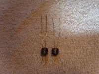
Here is a pic. The left one is a 32SR2S R2D batch no. and on the right is a 32SR2. Note the different ldr leg thickness, it is thicker on the "S" showing different manufacturing as well. When ever I order these I nearly always get the same batch no. Maybe one or two sneak in that are not, I just put them to the side for an order that does mate up with that batch no.
Cheers George
Cheers George
Attachments
Here is a pic. The left one is a 32SR2S R2D batch no. and on the right is a 32SR2. Note the different ldr leg thickness, it is thicker on the "S" showing different manufacturing as well. When ever I order these I nearly always get the same batch no. Maybe one or two sneak in that are not, I just put them to the side for an order that does mate up with that batch no.
Cheers George
George, with the sorted version, how many LDRs on average would one need to acquire in order to come up with a matched quad like you have described as using in the production Lightspeed?
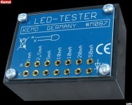
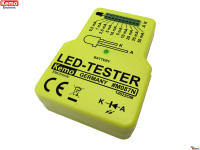
And you can match them like I used to in the early days using this $10 led tester primitive but effective way, and measure the resistances with an ohm meter, just don't use the 50mA range.
Cheers George
Cheers George
Attachments
Last edited:
A couple of things have come together to give me a new insight and I thought I’d pass it along for others to consider.
In re-reading the article about LEDs that I recently posted the URL for, I got reacquainted with LED characteristics and that information jelled with some other information I’ve acquired in a search for the appropriate capacitor to use in the control circuit for my LDRs.
First, LEDs are current-driven devices. The only way to control them with accuracy and consistency is by controlling the current that passes through them and not the voltage that is applied to them. Second, for LDR applications in audio, current must be controlled at a very fine level – on the order of one micro-amp. Third, in researching capacitors, I find that film capacitors have very low DC leakage but are typically only available in capacitances up to about 2uF. Electrolytic and tantalum capacitors are available in much larger values, but it turns out they are notoriously leaky, and tantalums are about as bad as electrolytics in this area – in other words, current flows between their anodes and cathodes at a fairly high rate.
Put that together , and you come up with this: never put an electrolytic or tantalum capacitor in parallel with the LED of an LDR, because it will create an alternate path for current to bypass the LED due to the leakage through the capacitor and that will adversely affect your ability to accurately control the current flowing through the LED in the LDR.
I think the best approach to designing a circuit to control the LED in an LDR is to go totally minimalist in the control path – you need a clean power source and precision current control. The fewer additional components in the circuit, the fewer places for current to wander off through and get lost. George’s circuit is good this way – no capacitors to muddle the current allocation through the LED -- just the potentiometer and LDR and possibly a trimmer.
Last edited:
makes perfectly good sense but..
wapo54001,
Your argument is logical and well thought out. However, build the attenuator using the simple circuit. Then solder 150uf OSCON SEP caps right on the power supply leads of each optocoupler. Listen again. I guarantee you will leave the caps in place.
To your argument however, perhaps it will sound even better if the Oscons are replaced with very low leakage PPE smt film caps. You could never get 150u. But a few 1uf smt caps might be interesting.
- Home
- Source & Line
- Analog Line Level
- Lightspeed Attenuator a new passive preamp