AndrewT - why don't we ever get to see your amp designs and builds? I'm sure many readers would like to see your work, know what problems and fixes you've faced.
Can you point me to some posts of your work? Maybe a thread of your amps? Thanks.
Can you point me to some posts of your work? Maybe a thread of your amps? Thanks.
Instruction? Just curiosity - a question. I'd like to see your work, other folks probably would too.
I have posted a few pics and included attachments of some of my work.
Admittedly only a tiny proportion of my postings.
Admittedly only a tiny proportion of my postings.
The Zobel (R+C) located before the output inductor MUST be at the output of the amplifier.
It MUST be located to minimise the impedance of the route that the output currents take in getting from the Power rails through the Zobel back to the power rail. That makes the location VERY close to the power terminal of the output device and the Power Ground terminal of the HF & MF decoupling.
The more I repeat this bit of advice the more I become convinced that this minimising of the impedance of the Zobel is vitally important to the performance of the amplifier.
Have other Members found evidence that supports my thoughts?
The discussion is not where to put zobels - this is well known.
There is distortion introduced AFTER coil. Maybe the coil is suboptimal dimensioned. If we take a look at latest simulation file you can see a zobel 0.µ/10R at amplifier output followed by 0.9µH coil with parallel 10R then 10 inch cable to the rear side of amplifier followed by an output relais and second zobel directly at output terminals. Relais seems to be not the reason as input and output distortion is the same...
My question to the community simply was
"Is it possible that at high frequency (> 10 kHz) and high output levels (~ 40V rms) the output coil is adding distortion?"
BR, Toni
The Zobel (R+C) located before the output inductor MUST be at the output of the amplifier.
It MUST be located to minimise the impedance of the route that the output currents take in getting from the Power rails through the Zobel back to the power rail. That makes the location VERY close to the power terminal of the output device and the Power Ground terminal of the HF & MF decoupling.
The more I repeat this bit of advice the more I become convinced that this minimising of the impedance of the Zobel is vitally important to the performance of the amplifier.
Have other Members found evidence that supports my thoughts?
Absolutely. However this is not the full picture. I am currently struggling with an LFET output stage that needs a very specific snubbing scheme around the outputs. What matters is the total loop inductance from collector to emitter. In other words, collector inductance is in series with RC inductance and both need to be minimized. If your collector decoupling is not close to the transistors, then minimizing RC length to ground won't help much. The RC return should go directly to the collector decoupling.
...
The RC return should go directly to the collector decoupling.
This is already fulfilled by the current pcb. The distortion rising starts directly after output coil.
I think the coil must be picking up the magnetic fields of the outputs, hence my suggestion to remotely locate the coil. Many people fear the coil radiating distortion into the surrounding circuitry but apparently it's the other way around in this case.
Hi Toni,
Where is R84 located in relation to the coil? I wonder if it can act as iron core and saturate?
Btw. Very nice work.
Mogens
Where is R84 located in relation to the coil? I wonder if it can act as iron core and saturate?
Btw. Very nice work.
Mogens
Good point. I always cringe when I see someone wrap the output coil around a resistor. It would be great if you could test the sensitivity of THD to metallic objects near the coil. Please? 🙂
The discussion is not where to put zobels - this is well known.
There is distortion introduced AFTER coil. Maybe the coil is suboptimal dimensioned. If we take a look at latest simulation file you can see a zobel 0.µ/10R at amplifier output followed by 0.9µH coil with parallel 10R then 10 inch cable to the rear side of amplifier followed by an output relais and second zobel directly at output terminals. Relais seems to be not the reason as input and output distortion is the same...
My question to the community simply was
"Is it possible that at high frequency (> 10 kHz) and high output levels (~ 40V rms) the output coil is adding distortion?"
BR, Toni
I think the 10R resistor value is too high, try in the range from 2R and 5R.
You shouldnt underestimate the importance of not only where the zobel is located but also the direction it is placed with regards to the pcb, output transistors and even the transformer. As an example having it at 90 degrees with regards to transformer can be detrimental in some cases compaired to having it at 180 degrees. Using flat copper wire for the coil also helps minimize magnetic pickup but is hard to find.
I think Self has some writings about coil characteristics and effects.
... found one major cable routing problem.😀
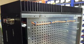
I have erroneously routed the speaker output cable from pcb parallel to the power supply wires about 4 inches. The power bjt switching spikes (~ 1Vpp / 20kHz) from power rails have had a chance to crosstalk into speaker cable ...
At those very low distortion levels at those high output power levels the cable routing inside the case is extremely sensitive. 😉
The speaker output cable is now routed under the mounting plate - see picture.
BTW coil and resistor are parallel but resistor is NOT inside coil.
Thank you all for your tips - every small step can help us DIYers to get the most out of our amplifier.🙂
Now have to measure again and again and again ...
Attachments
Thanks!Hi Toni,
Where is R84 located in relation to the coil? I wonder if it can act as iron core and saturate?
Btw. Very nice work.
Mogens
Coil is parallel to 10R. The 10R is a metal film 3W low inductance. But your hint with iron core may be helpful - about 3/4 inch away from the coil is an iron screw M4 - will remove it during tests.😉
you mean the 10R parallel to coil should be lowered?I think the 10R resistor value is too high, try in the range from 2R and 5R.
...
no !!!!... found one major cable routing problem...............
The speaker output cable is now routed under the mounting plate - see picture.
a single Flow or Return cable passing through a hole is not allowed. Does it make a current transformer? Or is it some other effect?
Both the FLOW and Return must pass through the same hole if it must through a hole at all.
But why have you got a single wire. It should be a twisted pair !!!!!!
That pair is both resistant to picking up interference and is good at not transmitting interference.
Always close couple Flow and Return Pairs. Always. That is what makes Planes good. The close coupling of the Flow and Return currents. In wire connections twisting achieve similar.
Thanks! Can you point me to some?I have posted a few pics and included attachments of some of my work.
Sorry for the OT.
They are not worth searching for, unless you specifically need to refer to that specific attachment.
If you have a specific need I could try to repost if I still have it.
If you have a specific need I could try to repost if I still have it.
Rod Elliot has written briefly about higher distortion after the output coil. Check the article about a classic 60 Watt amplifier on his site.
As someone has already pointed out, 10R is too high. IIRC Self advocated 1R.
You can always have one Zobel on the amp board, Coil with parallel snubber R off the amp board, close to the output terminals, followed with a second Zobel right on the output terminals. I am not able to recall the author, month/year etc., but there was an article in Electronics World about how to correctly dimension the second Zobel.
As pointed out by Andrew, the signal and return cables should run together in some geometrical arrangement which rejects Common Mode artifacts and preferably low inductance type. If you are familiar with weaving CAT5 wire as Speaker cable, you could try it. I am sure you will have much better results.
no !!!!
a single Flow or Return cable passing through a hole is not allowed. Does it make a current transformer? Or is it some other effect?
Both the FLOW and Return must pass through the same hole if it must through a hole at all.
But why have you got a single wire. It should be a twisted pair !!!!!!
That pair is both resistant to picking up interference and is good at not transmitting interference.
Always close couple Flow and Return Pairs. Always. That is what makes Planes good. The close coupling of the Flow and Return currents. In wire connections twisting achieve similar.
Hear! Hear!
Get your coil and its parallel resistor off the output PCB and as far as possible away from things like power-supply cables and anything made of iron or steel.
What are you using as a load when testing? Any non-linearity in the load will cause a non-linear current to flow which will then drop a non-linear voltage across the output coil and wiring, causing higher distortion readings after the coil.
How about a toroidal output coil? It shouldn't be hard to take the existing coil and bend it into a circle and glue the end together or use a zip tie. That might fix all of this.
I found a 16-foot piece of severed RG6 coax lying on the ground one day. Very stiff stuff with a braid+foil shield and thick copper core. I can't solder to the braid or the foil though.
I found a 16-foot piece of severed RG6 coax lying on the ground one day. Very stiff stuff with a braid+foil shield and thick copper core. I can't solder to the braid or the foil though.
- Home
- Amplifiers
- Solid State
- 2stageEF high performance class AB power amp / 200W8R / 400W4R