The FACT that you are hearing differences tells me that at least some of your cap swapping guessing is creating an amplifier that is FLAWED..
How many times do I need to repeat this same message?
Please repeat it all you like--that still doesn't make it true. If you have a theory, we would like to see some proof of it before we alter our belief system accordingly. Simply shouting it ad nauseum is not sufficient.
Replacing a cap does not make an amplifier or anything else flawed unless the inserted part's values are incorrect. It sounds different because the part sounds different. There is no known way to prove that with measurements. Some people will never accept it, which is their loss. It is pointless to debate.
If greater physical size is the factor which determines that a capacitor performs poorly in this amp, why are all the subjectively "better" caps, especially film and foil, larger? I cannot grasp the logic of this theory. The worst cap I heard in this design was the compact one shipped with the original kits, some metalized poly junk, literally the cheapest part available. It fit directly against the pads with virtually zero lead length. The best sounding cap (TC, so far) has leads that are more than an inch long, with another pigtail soldered between it and the board. It makes recorded music sound more real, if that is a flaw. Draw your own conclusions; I don't have any theories to offer.
Peace,
Tom E
Hi Tom, We are all eagerly awaiting your reports/impressions on the FE. Any info on your build progress?
Speaker Protection Modification
Since we didn't get any comments from experienced circuit designers on the speaker DC protection circuit modification that I proposed, I'm hoping that a few of you will try building the modification. This also works, with a different physical layout on other My_Ref boards. Hopefully, some of you guys that have built more than one FE pair will give it a try to give people confidence.
Here are the details.
The current speaker protection kicks open the relay at about +5.5 V DC. The negative voltage side kicks out at a higher voltage that seems to depend on the transformer, the better the transformer, the higher DC allowed or the worse the protection.
The modified circuit causes the relay to open at approximately 1.7 V DC, positive or negative. It does this by specifically adding a transistor circuit to handle the negative voltage side and by adjusting a voltage divider.
If you build this modification, you don't change anything in the signal path, but improve your speaker protection by making it more sensitive.
Just in case your are curious, the original circuit and the modified circuit has been calculated, simulated, and tested in hardware. The voltage numbers above are from building that part of the circuit on a board and testing it by itself. I don't recommend back feeding DC into a working amplifier.
BOM
1 each per board
PNP transistor - I used a 2n4403 because it is easily available (In stock at Mouser)(US builders can buy a 15 pack of PNP transistors for about $3 at Radio Shack. It includes 5 of the 2N4403).
150 Ohm resistor - 1/4 watt - axial lead - any type or tolerance (180R would also be OK)
47k Ohm resistor - 1/4 watt - axial lead - any type or tolerance (Note: a 39k or even 33k would work OK. They would slightly increase the relay opening voltage. For example, 33k would open at 2.2 V DC)
DIRECTIONS
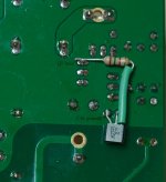
Find and remove R16 (75k). It is no longer needed.
Find and remove R19 (10k). Replace it with the 47k resistor.
Locate C15 (22 uF electrolytic) on the bottom of the board. Bend the lead of the 150 Ohm resistor about 90 degrees and test fit the 2N4403 and the 150R resistor so that the leads can reach the terminals shown in the photo.
After trimming the leads on the 150R, solder it to the emitter of the 2N4403. Insulate the emitter/resistor lead so that it doesn't short other pads on the board. I used shink tube, but tape will work as well.
Solder the collector of the 2N4403 to the ground connection of C15.
Solder the base of the 2N4403 to the plus terminal of C15.
Solder the free end of the 150R resistor to either the base of Q1 or the emitter of Q2.
Trim leads and you are done. I would be happy to answer any questions.
Jac
Since we didn't get any comments from experienced circuit designers on the speaker DC protection circuit modification that I proposed, I'm hoping that a few of you will try building the modification. This also works, with a different physical layout on other My_Ref boards. Hopefully, some of you guys that have built more than one FE pair will give it a try to give people confidence.
Here are the details.
The current speaker protection kicks open the relay at about +5.5 V DC. The negative voltage side kicks out at a higher voltage that seems to depend on the transformer, the better the transformer, the higher DC allowed or the worse the protection.
The modified circuit causes the relay to open at approximately 1.7 V DC, positive or negative. It does this by specifically adding a transistor circuit to handle the negative voltage side and by adjusting a voltage divider.
If you build this modification, you don't change anything in the signal path, but improve your speaker protection by making it more sensitive.
Just in case your are curious, the original circuit and the modified circuit has been calculated, simulated, and tested in hardware. The voltage numbers above are from building that part of the circuit on a board and testing it by itself. I don't recommend back feeding DC into a working amplifier.
BOM
1 each per board
PNP transistor - I used a 2n4403 because it is easily available (In stock at Mouser)(US builders can buy a 15 pack of PNP transistors for about $3 at Radio Shack. It includes 5 of the 2N4403).
150 Ohm resistor - 1/4 watt - axial lead - any type or tolerance (180R would also be OK)
47k Ohm resistor - 1/4 watt - axial lead - any type or tolerance (Note: a 39k or even 33k would work OK. They would slightly increase the relay opening voltage. For example, 33k would open at 2.2 V DC)
DIRECTIONS
Find and remove R16 (75k). It is no longer needed.
Find and remove R19 (10k). Replace it with the 47k resistor.
Locate C15 (22 uF electrolytic) on the bottom of the board. Bend the lead of the 150 Ohm resistor about 90 degrees and test fit the 2N4403 and the 150R resistor so that the leads can reach the terminals shown in the photo.
After trimming the leads on the 150R, solder it to the emitter of the 2N4403. Insulate the emitter/resistor lead so that it doesn't short other pads on the board. I used shink tube, but tape will work as well.
Solder the collector of the 2N4403 to the ground connection of C15.
Solder the base of the 2N4403 to the plus terminal of C15.
Solder the free end of the 150R resistor to either the base of Q1 or the emitter of Q2.
Trim leads and you are done. I would be happy to answer any questions.
Jac
Attachments

I was but my smartphone kept vibrating with such posts.... 😉
I admit that I'm a bit suspicious about the salsa dancing. I can't feel my phone vibrate when I'm sitting in a meeting, much less when dancing. 🙂
Jac
Jac,
A fascinating and valuable modification for those who have amps directly coupled to drivers. I have turned these amps off and on more than a thousand times over the years and never heard anything from the speakers, so I guess xover caps are protecting them. With active xovers before the amp, your mod would be essential.
Bob,
I haven't built my FE's yet because I don't have the funds to procure the quality parts I want to use.
All,
I am in contact with Parts Connexion about availability of Mundorf MLGO caps for C9, with a group buy in mind if others are interested.
The other candidate I am considering is a Jensen Axial electrolytic. It could be fit onto the FE board with a little care and an "outboard" connection to R10. I don't know anything about their sound, but Jensen caps are used in some heavyweight equipment. They might be just plain bipolar caps with a fancy wrapper and high price. I am not comfortable with using a low volatge BG there, and no other 'lytics sound as good to me, so the search goes on.
If I didn't already have two pairs of MyRef amps, I'd be more eager to get going. The FE PCB's sat on my kitchen table for a couple months, and I finally hid them in the basement so their emptiness wouldn't taunt me.
When I get around to building them, you'll be the second to know.
Peace,
Tom E
I have been through this before.Andrew, It would appear to me that if an amp with zero "Flaws" could be built - it would exist and everyone would be using the same set of circuits. What is the definition of that term in this situation?
Change the cap and you are possibly/probably changing the "complex" impedances of the various parasitics of those capacitors.
Simply using money to invent more guesses at which capacitor might give an improvement, is the wrong testing philosophy.
Try to get a handle on WHY the sound changes. Then take steps to eliminate what is bad about the sound change. Maybe then the Group can home in on the less damaging topology of capacitor combinations.
Tom, I thought we were looking at the same item till I realized a spelling difference. From another thread I got a reference to Jenzen - a developer who uses many caps in addition to the Jansen brand. It's mostly speaker stuff but I enjoyed his little spiel and pics on cap construction. Please add me to your GB list if it develops.
I'm in a similar situation with the final FE build. The RCs are sounding great so it's not essential that I rush the next version. I too have more MyRefs than a rational person needs. As a matter of fact - more amps than I'll ever use - period . Hope to start selling soon.
Let me take this opportunity to fill in some information mentioned in earlier posts that's related to all this. My first chunk of new (thirty year gap) DIY was all LM3886 based. Though being supper happy with the results, I was aware of other approaches that consistently received high praise. As I understood there was:
1. Other chips - e.g. TDA
2. Class D
3. Tube
4. Discrete Class A
So I embarked on a quest to build as many reasonably priced examples as I could afford to have the opportunity for real world, in-house comparisons.
The TDA7294 was a real surprise. It packs a lot of dynamic, musical and clean sound into a two channel package costing as little as $25 (boards and parts on eBay) I was so impressed I opened a thread dedicated to an attempt to squeeze out better performance in headroom and lower distortion at higher sound levels. That's still a work in progress and thankfully has been held together by Daniel W - still looks promising.
Haven't done anything with Class D. From what I read, that implementation seems better suited to home theater applications, and really not in the same category as the MyRefs in general and the FE specifically. Not sure if I will ever go there.
Though highly respected, tube amps appear to be just too delicate and difficult to maintain top performance for my everyday use. No doubt they are a universal standard to which most amps are/were compared, but the cost of the best of class is well beyond my budget. Fortunately I have a couple friends who own them and let me do those comparisons on occasion.
So the discrete Pass style Class A amps is where I've done the most investigation beyond the LM3886 world. I built the Amp Camp intro version first. Again at ~ $30 it's a great way to get a taste of Class A performance. There isn't a lot of power there but one can easily hear the tonal character that Class A proponents value. Next was the popular F5, which many consider the ultimate combination of quality sound, simplicity and bang for the buck. I was initially intimidated by what I perceived as a detailed and delicate set-up procedure, but soon learned the "KISS" principle was well in place. The ACA and the F5 sound very similar to me. They are smooth and relaxed with a stable and mostly distortion free presentation. I completely understand why that, I'll call it "straight wire" design appeals to so many.
My current and final adventure is a Burning Amp BA-3. It has a more complex front end, separate bias devices and interchangeable output boards. It promises (to my understanding) to introduce a more precise tuning and possibly a fuller - more extended spectrum compared to the ACA and F5.. As many of you know, I've been investigating liquid cooling for power amps and the BA-3 is the last leg of that challenge. Another work in progress, but appears promising and useful for reducing the bulk of heat management with high temp builds.
Somewhere along the way I also built a Class AB from my favorite eBay vendor that is a clone of the Honey Badger. I'll just call it similar to the BA-3 but with the front end, biasing and 12 output transistors all on one PCB. Daniel W. described it as a "Concert Amp" - new term for me - and it seems to combine some of the best elements of both the LM3886 and Class A designs. Of all the projects, it comes the closest to the musicality and dynamics of the MyRef family. It was also a part of the liquid cooling efforts.
So what have I learned from these adventures? I can honestly say I feel there is no such thing as "The Best Power Amplifier". There are just too many components, personal preferences and varying budgets for such a thing to exist - IMHO. I have come to respect and appreciate what the Class A designs offer and will most likely keep one of the builds. I can also say that Dario's FE remains my favorite and most enjoyable. I think Ivan summed it up the best...."this amp is PURE MAGIC". It appears some new developments like Roender's FC-100 prototype are seeking similar response/performance, but I've seen nothing close to the simplicity of the single board, low temp, flexible installation/configuration high quality solution provided by the FEs.
I'm glad I took the time to follow this path. I have learned a lot of fun new things, met some great forum contributors and thoroughly enjoyed it all. Hope this little summation is beneficial to others who have "the wandering eye" in the DIY audio world. I'll soon be clearing out the shelves and collecting my pennies for that ultimate FE build just like Tom is doing.
Kudos, Mr. D
Last edited:
Jac,
A fascinating and valuable modification for those who have amps directly coupled to drivers. I have turned these amps off and on more than a thousand times over the years and never heard anything from the speakers, so I guess xover caps are protecting them. With active xovers before the amp, your mod would be essential.
Peace,
Tom E
Tom,
I also don't have any sound on turn on or off, even though I am directly coupled to my speakers. My understanding of the speaker protection circuit isn't for transient thumps, it is to protect the speakers in case a component in the chain fails and introduces DC voltage that would tear apart the speaker.
When we build a new amp, we test the DC offset before we attach a speaker to avoid this problem. Eventually, when parts get old, some component will fail and the possibility a speaker damaging DC voltage will show up in the failure mode. While this circuit does introduce a short turn on delay, I view it's main value as protecting the speakers in the event of DC. The main thing my mod does is to protect the speakers at 1.7 volts instead of 5.5 volts.
Jac
As many of you know, I've been investigating liquid cooling for power amps and the BA-3 is the last leg of that challenge.
I have come to respect and appreciate what the Class A designs offer and will most likely keep one of the builds. I can also say that Dario's FE remains my favorite and most enjoyable.
So Bob, what do we call a liquid cooled BA-3? Maybe the BAA BLAT? A sound that a sheep might make?
Thanks for the update on your projects and what you have learned. I've been curious (but much slower) about many of the same things. I was really happy to read about your journey and conclusions.
Jac
So Bob, what do we call a liquid cooled BA-3? Maybe the BAA BLAT? A sound that a sheep might make?
Jac
"Back in the Day" I got caught up in the Commodore Amiga computer to about the same degree as these amps. Needing both more peripherals and better consolidation, I developed and produced the Bomac Tower. Both the Amiga and the company that did the actual automated metal bnding, Spectra Products, are now defunct. If I can get it right and there is enough interest, we might see the "BT-II" somewhere down the line.
A big overshoot and not necessary for the FEs - as evidenced by Dario's now famous favorite heatsink 🙄
Attachments
A "What If" that is pretty far off topic
Tom E,
Here is a thought that is probably outside of your zone of interest, certainly one that leaves the traditional My_Ref path, but one that I have thought about from time to time.
Let's say that the goal is to get a better cap in C9 position, hopefully one that is naturally non-polar like a film cap.
The way this works is that R7 and R10 provide the gain setting for the FE. C9 and R10 form a high pass filter that increases in impedance at low frequencies and reduces the gain of the LM318 op amp for better stability at low frequency. As long as R x C of that filter remain constant, the filter's corner frequency remains the same. In the case of C9 and R10, that corner frequency is 1.86 Hz.
If I want to keep the gain the same, R7/R10 needs to stay about 30:1. That means I can theoretically increase R7 and R10 and decrease C9 without changing the base circuit. For example, if I change R10 from 390 to 3.9k, then R7 becomes 120k, and C9 becomes 22 uF. That is at least possible for a film cap.
Let's say that I don't need 1.8 Hz, but could live with 5 Hz for the filter. Using R10 of 3.9k, C9 becomes 8 uF. That looks better still. I can imagine taking this further, maybe a 10 Hz filter and 4 uF for C9. This is also possible, but may introduce some phase shift in the bass area.
Maybe I don't need the full gain of 30:1 or 29.7 dB. Let's say I have an active pre-amp or really efficient speakers and can afford to give up 3 dB of gain. If I leave R7 at 120k and make R10 at 5.6k, I have a gain of 26.6 dB. If I use 10 Hz corner frequency, my C9 only needs to be 2.7 uF. At 2.7 uF there are lots of choices from small bi-polar lytics to lots of film caps.
Of course, this is oversimplified. I'm sure that you would want to tweak C10 and C32. I can't predict what other affects on sound would be. At the very least, we are risking more noise from R7 at 120k. But in the end, the advantages offered by replacing an electrolytic with a film cap might be worth any tradeoffs.
Just a thought.
Jac
I am in contact with Parts Connexion about availability of Mundorf MLGO caps for C9, with a group buy in mind if others are interested.
The other candidate I am considering is a Jensen Axial electrolytic. It could be fit onto the FE board with a little care and an "outboard" connection to R10.
Peace,
Tom E
Tom E,
Here is a thought that is probably outside of your zone of interest, certainly one that leaves the traditional My_Ref path, but one that I have thought about from time to time.
Let's say that the goal is to get a better cap in C9 position, hopefully one that is naturally non-polar like a film cap.
The way this works is that R7 and R10 provide the gain setting for the FE. C9 and R10 form a high pass filter that increases in impedance at low frequencies and reduces the gain of the LM318 op amp for better stability at low frequency. As long as R x C of that filter remain constant, the filter's corner frequency remains the same. In the case of C9 and R10, that corner frequency is 1.86 Hz.
If I want to keep the gain the same, R7/R10 needs to stay about 30:1. That means I can theoretically increase R7 and R10 and decrease C9 without changing the base circuit. For example, if I change R10 from 390 to 3.9k, then R7 becomes 120k, and C9 becomes 22 uF. That is at least possible for a film cap.
Let's say that I don't need 1.8 Hz, but could live with 5 Hz for the filter. Using R10 of 3.9k, C9 becomes 8 uF. That looks better still. I can imagine taking this further, maybe a 10 Hz filter and 4 uF for C9. This is also possible, but may introduce some phase shift in the bass area.
Maybe I don't need the full gain of 30:1 or 29.7 dB. Let's say I have an active pre-amp or really efficient speakers and can afford to give up 3 dB of gain. If I leave R7 at 120k and make R10 at 5.6k, I have a gain of 26.6 dB. If I use 10 Hz corner frequency, my C9 only needs to be 2.7 uF. At 2.7 uF there are lots of choices from small bi-polar lytics to lots of film caps.
Of course, this is oversimplified. I'm sure that you would want to tweak C10 and C32. I can't predict what other affects on sound would be. At the very least, we are risking more noise from R7 at 120k. But in the end, the advantages offered by replacing an electrolytic with a film cap might be worth any tradeoffs.
Just a thought.
Jac
Last edited:
Lehmanhill,
I can afford to give up 10db+ of gain and I'm using passive attenuation.
Do you have any suggestions for me to help lower the gain?
I'd also like to thank you for the update on the speaker protection circuit. I am going to convert all 4 of my FE's, better safe than burnt coils.
I can afford to give up 10db+ of gain and I'm using passive attenuation.
Do you have any suggestions for me to help lower the gain?
I'd also like to thank you for the update on the speaker protection circuit. I am going to convert all 4 of my FE's, better safe than burnt coils.
Jac,
Your understanding of this circuit and your ability to describe it in terms that we can understand are exemplary. Thank you for that last post, and all the others you've contributed here.
I doubt that I'll start tweaking values of components that seem to work so well now, but you raise very interesting points of real value.
My skill level is low enough that I can only handle plugging in different parts until I find one that sounds best. That might be crude and sometimes expensive, but I'm satisfied with where it's gotten us so far.
You and Dario are far more adventurous than I am. I enjoy tinkering with flavorings for your recipes.
Peace,
Tom E
Lehmanhill,
I can afford to give up 10db+ of gain and I'm using passive attenuation.
Do you have any suggestions for me to help lower the gain?
damuffin,
I thought about reducing gain and came very close to it, but in the end I decided to follow the standard build. If you haven't already, I would recommend that you build it standard at first, then try modifying. To be honest, most of this group has not gone there, so you playing with this would make you a true DIY pioneer, at least in the is group.
That means that there are some risks in the unknown. I wouldn't be surprised if changing the gain would change the sound in some way. My opinion is that the stability would remain the same, but I can't say for sure. In other words, proceed carefully and at your own risk.
That said, here are the equations as I understand them and how I would go about changing the gain.
As mentioned in the earlier post, the voltage ratio of output/input is determined by R7/R10.
R7 = 12k, R10 = 390R, voltage gain = 12000/390 = 30.77 v/v
If you want to think of that in dB,
dB gain = 20*log (R7/R10) = 29.76 dB
We should take care that R7 and R10 don't get too high (current noise) or too low (more heat). Generally, I like to keep resistors in the range of 1k to 100k, but those are not fixed rules. If it were me, I might play with keeping R7 the same and increase R10 to reduce gain. That would minimize the affect on other components around R7, for example C10 and C32.
The other thing you have to plan is keeping the corner frequency of the filter formed by C9 and R10. The current corner frequency is about 1.8 Hz. Less than 5 Hz should be fine.
Frequency in Hz = 1/2*pi*R*C = 1/2*pi*390*220e-6 = 1.855 Hz
Let's say for example that you change R10 to 560R. To keep the same frequency, C needs to change to 153 uF, not a normal value. But maybe 120 uF would be available.
Hz = 1/2*pi*560*120e-6 = 2.37 Hz
I hope this helps.
Jac
From my last post, perhaps this is a little more clear.
Hz = 1/(2*pi*R*C) = 1/(2*3.14*390*220e-6) = 1.85 Hz
Sorry, I forgot the parenthesis.
Jac
Hz = 1/(2*pi*R*C) = 1/(2*3.14*390*220e-6) = 1.85 Hz
Sorry, I forgot the parenthesis.
Jac
Thanks Jac, this certainly does clarify the concerns with lowering the gain of the FE.
I think your implementation is worthwhile to try.
If Im following you correctly at (r10/560r) 21.43 v/v that should lower the output by 7-8db.
I think your implementation is worthwhile to try.
If Im following you correctly at (r10/560r) 21.43 v/v that should lower the output by 7-8db.
Hi all, I just compare last schematic of My Ref Fe with last schematic My Ref C,
the differences from the schematic :
- different power supply (regulator LM317, dioda Mur820/860 with zener)
- different voltage for LM318
- using BAV99W. for input LM3886
- there also several capacitor removed from My Ref C (like near V+ or V-)
and for relay I think it simillar
I have 2 big question,
1. please help me for understand what BAV99W used for.
2. and how can LM317 can produce negative voltage?? why not LM337?
Thank you
Bing
Hi Bing,
you can find answer for you questions in the opening post of the GB thread.
1. for the voltage limiter, see linked post.
2. LM317 is used as a CCS (see here), the zener and shunt trasistor regulate voltage.
you can find answer for you questions in the opening post of the GB thread.
I have 2 big question,
1. please help me for understand what BAV99W used for.
2. and how can LM317 can produce negative voltage?? why not LM337?
1. for the voltage limiter, see linked post.
2. LM317 is used as a CCS (see here), the zener and shunt trasistor regulate voltage.
- Home
- Amplifiers
- Chip Amps
- My_Ref Fremen Edition - Build thread and tutorial