Don't worry, we are aware of the thread.Get With it Moderators!!!
I'm already glad David wants to share the results, that's very friendly.
He could just put his time in research and never go trough the trouble of posting answers to our questions too...
So, thanks David. I'll sure follow the impressive progress here.
He could just put his time in research and never go trough the trouble of posting answers to our questions too...
So, thanks David. I'll sure follow the impressive progress here.
Hooray for Gerald Fry... one of the leading respected figures of this forum.
Yup.... I also detect that scent of commercial interest here. Indeed some of the miraculous improvements in THD at the outset caused my ears to perk.
I am keen on MF. And anybody who can tweak it using contemporary DSP and latest in accelerometers, well that is wonderful to learn about. So thanks to David for posting.
So long as we keep a nice balance by sharing information - even if it originates as a commercial teaser, that's OK, sort of. But teaser announcements without DIY details, as Gerald suggests, would be bad.
Ben
Last edited:
If you want finished stuff to work with then maybe you should go to the Vendors Bazaar or commercial sections.
Totally agree with Tranquility here. Keep up the good work 🙂
Here is how I mounted the accelerometer on my servosub version 2. I have never come around to finish it though. But a did some initial measurements and this was the best location. I avoided the flexing of the dust cap, I got rid of the imbalance with the opposite weight and the speaker also have a cleaner appearance without the wire in front
http://home.ebnett.no/armand/Pics/AccelMount1.JPG
Alternavive accelerometer mounting with 4g balance (1 Norwegian krone)
http://home.ebnett.no/armand/Pics/AccelMount3.JPG
The accelerometer comes nicely out by the terminals
http://home.ebnett.no/armand/Pics/AccelMount2.JPG
The dust cap does not appear "untouched" but a more patient person could do a better job
Maybe it was just fallacy on my part, but looking at the CSD measurement (mic near dustcap) I though that the cone movement should be reasonably homogeneous up to 1kHz with this particular cone (polymer graphite yada yada), or least not less than a generic 18" can be up to 200Hz.How did you measure different movement around parts of the cone?
And the way sound from different parts of the cone meet and add or interfere with one another, different at each wave-length?
Reading your answer and experiment results it looks like I was probably wrong 😱
No it's only for bass. There is no benefit to be gained with midbass except for using current drive but then then you to be careful of the peak in the response.
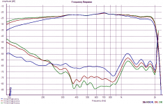
In my current drive experiment (voltage drive amplifier with inline resistor) I found that midband distortion was reduced (especially with an old motor without rings and all the modern stuff), but there was still a steady rise in distortion in the low range, directly proportional to excursion (in the attached curves you can see a rise in distortion in the lows with current drive, but it is only due to the rise in level in this range, following the rise in impedance when approaching resonance...)
Would not MF be able to also reduce this form of distortion, enabling the driver to be used lower (ideally 100 or 150Hz, instead of 300Hz...) ?
Attachments
Hooray for Gerald Fry... one of the leading respected figures of this forum.
Yup.... I also detect that scent of commercial interest here. Indeed some of the miraculous improvements in THD at the outset caused my ears to perk.
I am keen on MF. And anybody who can tweak it using contemporary DSP and latest in accelerometers, well that is wonderful to learn about. So thanks to David for posting.
So long as we keep a nice balance by sharing information - even if it originates as a commercial teaser, that's OK, sort of. But teaser announcements without DIY details, as Gerald suggests, would be bad.
Ben
I don't think a board of this complexity with 0402 surface mount components and 176 pin quad flat packs with 0.5mm pin spacing lends itself well to diy.
look at this project as a semi open source project which means that whilst the hardware and software used on the board is proprietary the use of third party speakers, accelerometers, amplifiers etc is not. This means that as long as the board supports a particular piece of external hardware then you can source this directly from the vendor themselves.
As for it being a commerical teaser that depends a lot on whether or not it gets finished. I have already spent a lot of time and money on it and have not made one cent from it !! If anyone has ever developed with Analog Devices SHARC DSP's will know that the tools are not cheap and I don't think diyers would want to duplicate what I have done and purchase these tools and have to learn C++ etc !
The main motivation for this thread is to spawn debate and get some feedback which has already been quite valuable.
regards
david
Totally agree with Tranquility here. Keep up the good work 🙂
Here is how I mounted the accelerometer on my servosub version 2. I have never come around to finish it though. But a did some initial measurements and this was the best location. I avoided the flexing of the dust cap, I got rid of the imbalance with the opposite weight and the speaker also have a cleaner appearance without the wire in front
http://home.ebnett.no/armand/Pics/AccelMount1.JPG
Alternavive accelerometer mounting with 4g balance (1 Norwegian krone)
http://home.ebnett.no/armand/Pics/AccelMount3.JPG
The accelerometer comes nicely out by the terminals
http://home.ebnett.no/armand/Pics/AccelMount2.JPG
The dust cap does not appear "untouched" but a more patient person could do a better job
That's neat having those pressure release holes in the cone which looks like you have passed the 3 pin connector directly through it without having to cut a hole in the speaker ! Is this a peerless driver is it ? I note that is has a very shallow voice coil former !!
I have also found the ACH-01 to be very temperature sensitive and you only have to blow air on it to generate a signal where it tends to introduce some very low frequency noise into the system. Have you found the same ? I will have to thermally isolate it completely from the voice coil and the dustcap will isolate it from the surrounding air.
Anyway the way you have done it would work directly with this board 😉
regards
david
Maybe it was just fallacy on my part, but looking at the CSD measurement (mic near dustcap) I though that the cone movement should be reasonably homogeneous up to 1kHz with this particular cone (polymer graphite yada yada), or least not less than a generic 18" can be up to 200Hz.
Reading your answer and experiment results it looks like I was probably wrong 😱
In my current drive experiment (voltage drive amplifier with inline resistor) I found that midband distortion was reduced (especially with an old motor without rings and all the modern stuff), but there was still a steady rise in distortion in the low range, directly proportional to excursion (in the attached curves you can see a rise in distortion in the lows with current drive, but it is only due to the rise in level in this range, following the rise in impedance when approaching resonance...)
Would not MF be able to also reduce this form of distortion, enabling the driver to be used lower (ideally 100 or 150Hz, instead of 300Hz...) ?
current drive is good at reducing motor distortion at high frequencies whilst also making it worse at low frequencies. However no feedback will fix up distributed resonances in the diaphragm since it only tries to correct at one point on the cone which is usually at the voice coil. The high frequency reproduction is still dependent on the construction of the cone and the material used which is why metal cones are favoured for this sort of application.
regards
david
David - could you please walk us through your first pair of charts (20 Hz) in simple language. I don't think I understand much about them. What are we looking at? Mic measurements? Why are there bumps above and below 20 Hz and every 20 Hz?
Thanks.
Ben
Thanks.
Ben
Last edited:
What are you are seeing is the spectrum sweep of the output of the accelerometer (not from a microphone which should be very similar) whilst the speaker is being driven from a built in sinewave generator without and with feedback applied. In an ideal world with no distortion you should only see a peak at 20Hz and nowhere else. The peaks at the multiples of the fundamental of 20Hz is indicative of distortion. So the 2nd harmonic distortion is at 40 Hz, 3rd is at 60Hz, 4th is at 80Hz etc. When feedback is applied you expect to see the level of the fundamental stay the same whilst the other peaks should reduce in proportion to the amount of feedback at that particular frequency which is what you are seeing in the second plot.
regards
david
regards
david
Last edited:
I think its a neat idea. i also think that if you build this truly for the DIY crowd how about considering kickstarter as a method to get this into the hands of the diy crowd (similar to the many arduino projects)? I for one would be interested, especially for car audio applications where distortions are caused by the mounting methods/space.
either way i am intellectually intrigued by the novelty of it and i hope you would let this become more of a collaboratively eco-system as you progress. i would put in a bit of coin into kickstarter if you decide to offer the complicated parts as diy but enable tinkerers like myself extend the idea (as i said, like the many arduino projects).
i'm not sure if that is commercial or diy, this kind of falls in-between imho. the discussion has elements of commercialism (in the areas of talking innovation, novelty, details) to it but also approaches it with a diy mindset (in the areas of extensability, allowing others to comment and critique, open sharing of how the ideas was developed etc). To me it smells just like the arduino projects that has some elements of commercialism with them but also allows for the diy'er to benefit by allowing the idea to be extended and superceeded by emphasizing shared knowledge and community.
my few cents...
par
I have also found the ACH-01 to be very temperature sensitive and you only have to blow air on it to generate a signal where it tends to introduce some very low frequency noise into the system. Have you found the same ? I will have to thermally isolate it completely from the voice coil and the dustcap will isolate it from the surrounding air.
regards
david
Yes, its a peerless 12" XXLS driver. I have not noticed the low frequency noise from the accelerometer. But I have never really looked for it either. Inspired by your efforts I have now dragged my MF subwoofer into my workshop and have started measuring phase etc. I will have a lookout for that low frequency noise. With my accelerometer glued to the voice coil I could be in big trouble! How do you suggest I test it? Maybe play really loud for 20 seconds for the voice coil to heat up and then monitor what happens?
Yes, its a peerless 12" XXLS driver. I have not noticed the low frequency noise from the accelerometer. But I have never really looked for it either. Inspired by your efforts I have now dragged my MF subwoofer into my workshop and have started measuring phase etc. I will have a lookout for that low frequency noise. With my accelerometer glued to the voice coil I could be in big trouble! How do you suggest I test it? Maybe play really loud for 20 seconds for the voice coil to heat up and then monitor what happens?
The spec sheet says that the accelerometer is very temperature sensitive. Even thermal air gradients cause problems. When you enclose it behind a dust cap it should be ok but I noticed that yours is butted up against the voice coil which could cause problems as the voice coil heats up and cools down. Obviously the best way is to completely isolate it from any thermal stimulus.
From the spec sheet
In an effort to keep the product cost low, the ACH01 uses a ceramic substrate as the mounting base. Because of this, the ACH01 is susceptible to base strain and temperature transient effects. A mechanically rigid and thermally nonconductive mounting surface is highly recommended to limit the side effects. MEAS application engineers are available to recommend various mounting arrangements for your specific application.
also what glue are you using ?
regards
david
I hope Gerald Fry (and other wise persons) are out there to correct my poor grasp of this but...What are you are seeing is the spectrum sweep of the output of the accelerometer (not from a microphone which should be very similar) whilst the speaker is being driven from a built in sinewave generator without and with feedback applied. In an ideal world with no distortion you should only see a peak at 20Hz and nowhere else. The peaks at the multiples of the fundamental of 20Hz is indicative of distortion. So the 2nd harmonic distortion is at 40 Hz, 3rd is at 60Hz, 4th is at 80Hz etc. When feedback is applied you expect to see the level of the fundamental stay the same whilst the other peaks should reduce in proportion to the amount of feedback at that particular frequency which is what you are seeing in the second plot.
regards
david
In the first chart, we are looking at a spectrum analysis of the signal coming from the accelerometer. It shows both the 20 Hz sine input as well as all the crap generated by EVERYTHING upstream and some downstream of the accelerometer (which includes the driver (driven hard to some unknown degree of duress), your trick circuitry decoding the accelerometer, DSP, faults of the accelerometer, shaking mounting, loose objects buzzing around the driver, etc.). As negative as I am about speaker distortion, it seems like David has posted a chart showing a mountain of distortion (which some readers may falsely attribute to the driver alone, perhaps thinking it is being dramatically over-driven).
In the second chart, we are looking at the accelerometer output with some degree of negative feedback applied. THAT negative feedback corrects EVERYTHING in the circuit whether (as in the first chart) it arose from the so-so drivers you are using, faults of the accelerometer, circuitry, loose buzzing objects shaking the set-up, DSP, etc. We don't know exactly what pieces of the loop are present in the first chart and second chart.
So David's impressive reduction of distortion by negative feedback includes the correction of many elements besides the driver and some of these distortions are introduced by David's own gizmo... and then reduced by negative feedback in the second chart.
It is a trivial chore to simply put a mic in front of the driver, before and after, and run it through the same spectrum analyzer. Even a cheap mic (or a Radio Shack SPL) should pick up those horrible spectral ghosts and illuminate (if not fully clarify) what happens with the MF applied.
Or I could be quite confused.
Ben
Last edited:
Yes I could put a mic in front of the speaker but because it is mounted in free air would give an erroneous result due to acoustic cancellation. What you are seeing from the accelerometer is attributable to the speaker alone since none of the other elements such as the accelerometer, DSP, ADC, DAC, amplifier etc exhibit anywhere near the same non linearities as the speaker. In fact the speaker is not good at reproducing anything below its resonant frequency and would not normally be used in hifi apps because of its high distortion.
The next test will be to put the speaker in a sealed enclosure and then run the same test with a mic. I will do this as a matter of course. I also have a good quality 18 inch driver designed for subwoofer apps which I shall test as well once I find a suitable enclosure to house it in.
regards
david
The next test will be to put the speaker in a sealed enclosure and then run the same test with a mic. I will do this as a matter of course. I also have a good quality 18 inch driver designed for subwoofer apps which I shall test as well once I find a suitable enclosure to house it in.
regards
david
current drive is good at reducing motor distortion at high frequencies whilst also making it worse at low frequencies. However no feedback will fix up distributed resonances in the diaphragm since it only tries to correct at one point on the cone which is usually at the voice coil. The high frequency reproduction is still dependent on the construction of the cone and the material used which is why metal cones are favoured for this sort of application.
So can I conclude that using MF for a midbass driver would give the same distortion reduction as pure current drive in the mid/high bands, and also reduce (part of) the mechanical (excursion related) distortion in the lower part of the band?
Also on another subject, can we expect MF to reduce sound "differences" between drivers, such as the ones associated with difference in mechanical resistance of the spider and surrounds (Rms) that are supposed to alter low level dynamic?
Could be.snip
What you are seeing from the accelerometer is attributable to the speaker alone since none of the other elements such as the accelerometer, DSP, ADC, DAC, amplifier etc exhibit anywhere near the same non linearities as the speaker. In fact the speaker is not good at reproducing anything below its resonant frequency and would not normally be used in hifi apps because of its high distortion.
snip
regards
david
But I look forward to seeing the mic results, hopefully powering the driver at a less flaky frequency and using nothing but a conventional amp set-up in the circuit in the "before" test.
Ben
So can I conclude that using MF for a midbass driver would give the same distortion reduction as pure current drive in the mid/high bands, and also reduce (part of) the mechanical (excursion related) distortion in the lower part of the band?
Also on another subject, can we expect MF to reduce sound "differences" between drivers, such as the ones associated with difference in mechanical resistance of the spider and surrounds (Rms) that are supposed to alter low level dynamic?
No you would not use mfb on a mid bass driver because they usually have much lower demands in terms of diaphragm displacement and so exhibit much lower distortion than a woofer that is used for the lowest octaves. Current drive is all you need but bear in mind the need to tame the response peak at the resonance frequency due to the high Q response you get from current drive 😉
And yes you could expect mfb to reduce differences in sound quality of woofers but there are other factors at play which mfb won't fix such as cone flexure, suspension noise and vibration modes. These are more to do with the physical manufacture of the device and can't be changed.
regards
david
I think its a neat idea. i also think that if you build this truly for the DIY crowd how about considering kickstarter as a method to get this into the hands of the diy crowd (similar to the many arduino projects)? I for one would be interested, especially for car audio applications where distortions are caused by the mounting methods/space.
either way i am intellectually intrigued by the novelty of it and i hope you would let this become more of a collaboratively eco-system as you progress. i would put in a bit of coin into kickstarter if you decide to offer the complicated parts as diy but enable tinkerers like myself extend the idea (as i said, like the many arduino projects).
i'm not sure if that is commercial or diy, this kind of falls in-between imho. the discussion has elements of commercialism (in the areas of talking innovation, novelty, details) to it but also approaches it with a diy mindset (in the areas of extensability, allowing others to comment and critique, open sharing of how the ideas was developed etc). To me it smells just like the arduino projects that has some elements of commercialism with them but also allows for the diy'er to benefit by allowing the idea to be extended and superceeded by emphasizing shared knowledge and community.
my few cents...
par
Yes you could classify it as sort of like an arduino device for audio except with a specific application in mind rather than a universal application 😉
However I have only seen one audio project on kickstarter which was a phono preamp so I am not sure how it would be accepted by the kick starter community.
Bugle2: A DIY Phono Preamp by Jim Hagerman — Kickstarter
regards
david
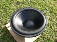
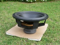
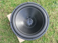
18 inch sub ready for a transformation !
IST Mach 5 IXL-18 ready for surgery !!
Images shown before and after the dust cover removed ready for the accelerometer transplant !! Next week I will build the accelerometer bridge and mount the accelerometer. Now all I need is a speaker box !!
IST Mach 5 IXL-18 ready for surgery !!
Images shown before and after the dust cover removed ready for the accelerometer transplant !! Next week I will build the accelerometer bridge and mount the accelerometer. Now all I need is a speaker box !!
Attachments

- Status
- Not open for further replies.
- Home
- Loudspeakers
- Subwoofers
- Low distortion, DSP based high gain servo controlled woofer controller.