Hi JKoch,
Nice work! Let me know if you have extra PCBs left and how much you'll sell them. I would probably be interested.
THanks
Do
Nice work! Let me know if you have extra PCBs left and how much you'll sell them. I would probably be interested.
THanks
Do
Hi pinnocchio
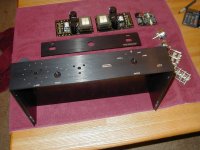
Thank you. I have just made it but not checked yet. I hope I will check all traces and connections till the end of this week. In next week I will send Gerber files to pcb's manufacturer and next get price for the pcb. It will be FR-4 2 mm thick laminate, double sided Cu 70um, gold plated. In my opinion it will cost not less than US$35/1pc. Exactly price I will give after receiving offer from manufacturer. How many pcb you want? The one pcb contains two rails (+/-) and two channel (left and right).
BTW Toshiba transistors: I have just received them. Thank you for support.
The Blowtorch power supply choke is a common mode choke in both the DC positive and DC negative lines. The center tap choke (1 to 3 mh) not needed in the Blowtorch keeps HF noise out of the ground, but dual bridges eliminates /reduces it even more. There are dual bridges in the Blowtorch supply for each channel.
JKoch did you find 2SK216/2SJ79 yet?
JKoch did you find 2SK216/2SJ79 yet?
Last edited:
Hi pinnocchio
Thank you. I have just made it but not checked yet. I hope I will check all traces and connections till the end of this week. In next week I will send Gerber files to pcb's manufacturer and next get price for the pcb. It will be FR-4 2 mm thick laminate, double sided Cu 70um, gold plated. In my opinion it will cost not less than US$35/1pc. Exactly price I will give after receiving offer from manufacturer. How many pcb you want? The one pcb contains two rails (+/-) and two channel (left and right).
BTW Toshiba transistors: I have just received them. Thank you for support.
I would take one for sure. Please let me know the price when you have it.
Thanks
Do
ticknpop:
Thanks for detail. Look on my schematic. I use two bridges and one common mode choke and next series resistors in each rails. Next are two el-caps with common ground. And one el-cap is connected between both rails before choke.
pinnochio:
OK. I will give you price after I receive the offer.
Thanks for detail. Look on my schematic. I use two bridges and one common mode choke and next series resistors in each rails. Next are two el-caps with common ground. And one el-cap is connected between both rails before choke.
pinnochio:
OK. I will give you price after I receive the offer.
Attachments
It is interesting that real audio improvement is being made here. The CTC Blowtorch power supply is very similar to what was just shown. Missing is a resistor across each choke coil leg, to critically damp the circuit.
Hi ticknpop
I have bought Hitachi 2SK216/2SJ79 on ebay:
1pair or 2pcs Transistor Hitachi to 220 2SJ79 2SK216 J79 K216 | eBay
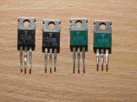
I hope they are genuine Hitachi. Building clone Krell KSA50Mk2 I was finding Toshiba 2SC2238-Y/2SA968B-Y. I examined and checked many pictures and offers from: electronic distributors, ebay and Chinese alibaba sellers. All of them offered 2SC2238-Y/2SA968B-Y in black TO-220 case. But original Toshiba P-channel/PNP TO-220 transistors were encapsulated in green case. Only used Toshiba/Hitachi transistors have green colour from Chinese sellers. All new 2SA968B were black. They are fake, I am sure. Finally I bought about 20 pairs of used 2SC2238-Y/2SA968B-Y. All were matched with success. Well I am sure they are genuine original Toshiba transistors. Similar situation concern Hitachi 2SK216/2SJ79. All new this type transistors offered on ebay and alibaba are in black cases. But they were encapsulated by Hitachi in black and green cases, so I hope the above ebay seller have original Hitachi transistors. I afraid if he will send me the same transistors as showed on ebay picture. I made special notice sending money that I interested in original black and greed transistors only. After I will receive them I let you know my opinion about the transistors (and the seller).
I have bought Hitachi 2SK216/2SJ79 on ebay:
1pair or 2pcs Transistor Hitachi to 220 2SJ79 2SK216 J79 K216 | eBay
I hope they are genuine Hitachi. Building clone Krell KSA50Mk2 I was finding Toshiba 2SC2238-Y/2SA968B-Y. I examined and checked many pictures and offers from: electronic distributors, ebay and Chinese alibaba sellers. All of them offered 2SC2238-Y/2SA968B-Y in black TO-220 case. But original Toshiba P-channel/PNP TO-220 transistors were encapsulated in green case. Only used Toshiba/Hitachi transistors have green colour from Chinese sellers. All new 2SA968B were black. They are fake, I am sure. Finally I bought about 20 pairs of used 2SC2238-Y/2SA968B-Y. All were matched with success. Well I am sure they are genuine original Toshiba transistors. Similar situation concern Hitachi 2SK216/2SJ79. All new this type transistors offered on ebay and alibaba are in black cases. But they were encapsulated by Hitachi in black and green cases, so I hope the above ebay seller have original Hitachi transistors. I afraid if he will send me the same transistors as showed on ebay picture. I made special notice sending money that I interested in original black and greed transistors only. After I will receive them I let you know my opinion about the transistors (and the seller).
Attachments
John, I have a serious doubts about Supertex VN0106N3-G/VP0106N3-G transistors. They can be obtained from Mouser but they are encapsulated in TO-92. I intend to fit them to custom made dedicated copper heat-sink but I afraid about their power dissipation. How do you think they have enough power to use them in JC-80 or I should replace them by other TO-220 transistors?
I have original , genuine Hitachi 2SJ79 in black bought at Farnell a few years ago. They are easy to test by measuring vgs since are the only MOSFET which have GSD footprint instead of usual GDS.If they are GDS , they are repacked fakes.
John, I have a serious doubts about Supertex VN0106N3-G/VP0106N3-G transistors. They can be obtained from Mouser but they are encapsulated in TO-92. I intend to fit them to custom made dedicated copper heat-sink but I afraid about their power dissipation. How do you think they have enough power to use them in JC-80 or I should replace them by other TO-220 transistors?
I`m not Him , sorry but maybe this helps : http://www.hifido.co.jp/KW/G0102/J/0-10/C09-47228-33257-00 (the "j" photo)
and I think these TO-92 trans (VN0106/VP0106) are way too small....
Last edited:
Sernikus, I afraid you have a right. They maybe to small. But in anyway I would be sure of that getting answer from John Curl. Thank you for the pictures. Each new picture give new details about JC-80.
servo and true balanced kit flaw
Hi JKoch and diyAudio fellows,
I am not sure about your intentions to use the PCB delivered by Stanton and/or other eBay vendors. Thanks to the kindness of Mr. Curl, having the original schematics, I could notice that the main purpose of this preamplifier was to take SE input and deliver balanced or SE output. My build suits this designed purpose, but I noticed that the kit promises true balanced input and this is an issue.
If I take the schematic of JKoch, published in http://www.diyaudio.com/forums/analog-line-level/206797-jc-80-ebay-pcbs-power-train-18.html#post3508673
I can see the intention to follow the kit design and in the same time JC published schematic. I will use the annotation from the schematic published in that post to prove my point.
The resistor used between ground and negative input is 100k (R7225). The resistor from the opamp that controls the imbalance between + and - outputs (IC7201) is just 1kOhm as in the original schematic (R7222).
In these conditions, you will have an impedance of 100k on the positive input, and less than 1k on the negative input, as we can consider the output of IC7201 to be 0 Ohms impedance point. This can be an issue...
The other thing, in case of balanced input you are using a servo that is acting directly in the signal path and this is against the philosophy expressed by Mr. Curl in the BT thread, and I fully agree with that. If you check the original schematic, R7225 is a 100 Ohms resistor, thus the servo has much less "authority" than the one presented in the kit.
If you use the preamp as original designed (SE input) there should be no worries... but I thought it's worthy to mention these points for the ones that intend to use it as a balanced input preamplifier. It might work (well enough), but it would be a VW, not a Porsche (to acknowledge the earlier promoted car analogy).
Of course, if John Curl would comment differently, I will defer my notification to whatever he says, as I'm talking about (a variation of) his own design.
I am interested to see other's opinion about this point. I would be sorry to learn that this was commented before and I just missed those posts. Sorry for a long reply from my side!
Cheers!
Hi metallicus69
You have a right. My first schematic include mistakes you mentioned in your post. It was my first rough schematic. Firstly I focused on power supply modules to finish them. But now encouraged by you I corrected the JC-80 schematic. I need SE Input and SE+Bal Outputs in my preamplifier, so the attached schematic has Bal Output. It will be design as a separately module which I will fit on bigger base output board. The output board will be included attenuator and output sockets (XLR, RCA and BNC). Thank you for your notice.
You have a right. My first schematic include mistakes you mentioned in your post. It was my first rough schematic. Firstly I focused on power supply modules to finish them. But now encouraged by you I corrected the JC-80 schematic. I need SE Input and SE+Bal Outputs in my preamplifier, so the attached schematic has Bal Output. It will be design as a separately module which I will fit on bigger base output board. The output board will be included attenuator and output sockets (XLR, RCA and BNC). Thank you for your notice.
Attachments
I have both green and black J79 that are real - Hitachi went to black cases for the last years of production... sometimes better to buy green case ones because less chance for fakes
WARNING! The TO-92 devices are the RIGHT DIE, but the wrong package! The original JC-80 was designed with TO-220 devices with the SAME DIE inside.
IF you can find a way to HEATSINK the TO-92 devices properly, perhaps they can be used in this application.
IF you can find a way to HEATSINK the TO-92 devices properly, perhaps they can be used in this application.
Thanks, John for this warning. I have data sheets for both VN0106 and VP0106 with encapsulation in TO-39, TO-52, TO-92, TO-220 and DIP-14.
But more thanks for confirmation that is possible to use TO-92 in this project. I can buy VN0106N3-G and VP0106N3-G in TO-92. I intend to hand-made special copper heat-sink for all TO-92 (4 pcs) to get thermal connection between them. After I finish the pcb I will publish it in the thread, of course.
But before to start designing pcb I need to find answer for important question: if I need unbalanced (SE) outputs, so I could connect -out to ground or I should find any other solution for better sound quality. Maybe someone give me any answer, please?
Attachments
Hi JKoch,
If you need SE output, you need to take the output signal between OUT+ and GND. I don't think your preamplifier would like shorting the OUT- to GND.
At least this is how I see it.
If you need SE output, you need to take the output signal between OUT+ and GND. I don't think your preamplifier would like shorting the OUT- to GND.
At least this is how I see it.
- Home
- Source & Line
- Analog Line Level
- JC-80 eBay PCBs & Power Train