for post 99
Yet another question - what will be an output impedance of this preamp?
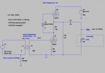
(Please note R7 10K does not belong to the amp, it is load's input impedance.)
Yet another question - what will be an output impedance of this preamp?
(Please note R7 10K does not belong to the amp, it is load's input impedance.)
I have been told that a rechargeable lithium at the cathode there charges its self up as you run the equipment. Its practically self sustaining! I also heard great reviews of the sonic properties this way.
--------------
Here is the THD for the capacitor layout:
Harmonic Frequency Fourier Normalized Phase Normalized
Number [Hz] Component Component [degree] Phase [deg]
1 1.000e+03 1.692e+00 1.000e+00 -179.15° 0.00°
2 2.000e+03 1.258e-04 7.435e-05 -77.24° 101.91°
3 3.000e+03 1.743e-05 1.030e-05 -177.79° 1.35°
4 4.000e+03 2.278e-07 1.346e-07 93.56° 272.71°
5 5.000e+03 2.654e-09 1.568e-09 0.17° 179.31°
6 6.000e+03 2.012e-09 1.189e-09 -171.28° 7.87°
7 7.000e+03 2.344e-09 1.385e-09 -175.14° 4.00°
8 8.000e+03 2.676e-09 1.581e-09 -176.20° 2.94°
9 9.000e+03 3.009e-09 1.778e-09 -177.56° 1.59°
Total Harmonic Distortion: 0.007506%
---------------------------
Here are the THD logs for the 1:1 trafo:
Harmonic Frequency Fourier Normalized Phase Normalized
Number [Hz] Component Component [degree] Phase [deg]
1 1.000e+03 1.392e+00 1.000e+00 -179.72° 0.00°
2 2.000e+03 9.790e-04 7.031e-04 89.48° 269.21°
3 3.000e+03 2.103e-06 1.510e-06 -1.59° 178.13°
4 4.000e+03 3.658e-09 2.628e-09 -105.98° 73.75°
5 5.000e+03 1.437e-09 1.032e-09 171.88° 351.60°
6 6.000e+03 1.640e-09 1.178e-09 -177.45° 2.27°
7 7.000e+03 2.055e-09 1.476e-09 174.43° 354.15°
8 8.000e+03 2.065e-09 1.483e-09 -177.99° 1.73°
9 9.000e+03 2.571e-09 1.846e-09 177.50° 357.22°
Total Harmonic Distortion: 0.070315%
-----------------
My wonder is its ability to sit in the middle of the signal path like how you have done. It can act as a neutral capacitor?
Results look very promising!I have been told that a rechargeable lithium at the cathode there charges its self up as you run the equipment. Its practically self sustaining! I also heard great reviews of the sonic properties this way.
Though I am hesitant to replace very simple atomic device - resistor - with quite complex device - battery - here on U1 cathode.
If the battery is self rechargeable, means it issues same amount of electrons as it consumes, so it can be theoretically diminished to some R and C (or some network of R and C). You can read this article to see how complex batteries are
http://www.google.ca/url?sa=t&rct=j...V5dcDWR64CEaKLw&bvm=bv.47008514,d.aWc&cad=rja
In case of biasing of U2 it would make sense because we remove capacitor and 2 resistors there.
Probably all these variants should be auditioned.
Is it about a battery or about a TF?My wonder is its ability to sit in the middle of the signal path like how you have done. It can act as a neutral capacitor?
Holly smokes, lithiums apear complex. It looks like it could be so susceptible to fluctuations. But at the same time, some folks swear by it. I have just came across this one forum page on the matter, good read but I didn't consolidate all my thoughts yet.
Battery Bias Mod - AudioKarma.org Home Audio Stereo Discussion Forums
Ohya I ment U2 grid (where you placed yours). I suppose that the cathode of U1 and the grid of U2 are both in the signal path. But I feel that U2 Grid would be more in the signal path? (less current thought too)
Honestly Im not 100% convinced of complex battery biasing, it just sounds bulky in concept
An LED is much simpler, gives a visual indication of circuit operation, and works extremely well (low impedance, low noise).
Holly smokes, lithiums apear complex. It looks like it could be so susceptible to fluctuations. But at the same time, some folks swear by it. I have just came across this one forum page on the matter, good read but I didn't consolidate all my thoughts yet.
Battery Bias Mod - AudioKarma.org Home Audio Stereo Discussion Forums
Ohya I ment U2 grid (where you placed yours). I suppose that the cathode of U1 and the grid of U2 are both in the signal path. But I feel that U2 Grid would be more in the signal path? (less current thought too)
Honestly Im not 100% convinced of complex battery biasing, it just sounds bulky in concept
That guy says "Another advantage is no AC can pass through a battery and it's a fixed bias, voltage, and current so there is no fluctuation.". This I do not think so. Regarding to SPICE circuit of lithium battery from article "Comparison of Several Methods for Determining the Internal Resistance of Lithium Ion Cells", chapter 2.3. AC Resistance, battery can conduct AC.
Chapter 4.9. Impedance Spectroscopy, Figure 10 shows that battery had 2.3mOhm of impedance at 1kHz, and, the most unpleasant, it produces gradual phase shift from 1kHz -10dgr, to 20kHz 40dgr.
I do not know how to make a model of a battery for spice, but may be we can replace it with equivalent circuit from the article.
or better to audition it? 😉
Regarding batteries as a signal conductor.
I've found article "Evaluation of Lithium-Ion Battery Equivalent Circuit Models for State of Charge Estimation by an Experimental Approach" and got DP model and element parameters from Table5. Battery is ~63V
Built simple SPICE circuit.
Simulation shows very low THD, flat FR and very low resistance.
It has tiny phase fluctuations above 10kHz.
It is all because huge internal capacitances were shunted by very low restances, so they practically had no impact.
So, it appears that battery can be used for biasing! And it conducts AC signal.
I am not sure though about how much noise is created by electrons going to ions and back to electrons there in electrolyte.🙂
Attachments
Fascinating! Is there really more than 5000 farads in this battery model? Is there really that many farads in a double-A rechargeable? Apparently this is all news to me.
This makes sense sonically because people who tried both batteries and LED's can't seem to stand the way LED's sound. Does that even make sense now that we are looking inside the structure of what makes a battery a battery? How can we physically (in this simulator) simulate the pros and cons of battery and LED's?
Im still having a hard time perceiving that a battery can produce a cleaner path than a capacitor, signal wise. Is this an exotic method? Is that why this isn't a more familiar approach?
With 1.5V battery I do not know what element's parameters are. Using a "common sense" I'd divide each by 45.🙄
I can see it should have very little impact.
Though the previous article "Comparison of Several Methods for Determining the Internal Resistance of Lithium Ion Cells" in Figure 10 shows phase shift in DEGREES! The circuit I've simulated shows phase shift in micro degrees.
I trust the model more, I think there is a typo in first article.
I do not think that it make sense to introduce battery as a sub-circuit into the schematic. Lets just use a standard "battery" element, just set appropriate resistance (I set 0.001 Ohm for 1.2V battery, works perfectly).
The latest schematic uses 2 batteries. 1.2V Li to bias U1 and 9V Li to bias U2.
I do not know what will be better NiCa or Lithium, but one guy wrote that NiMH have fast discharging rate (1%/day) so you should use preamp at leas once a week 🙂. I'd start with Lithium. (I also love the song by Nirvana)🙂
What's left?
- to calculate output impedance. It is better to be 600 Ohm to be compatible with other amps line inputs. Experts please help!
- to simulate noise
- to select an input TF from quality/price perspective
woodrough,
As a reference point, I ran an LTSpice simulation of a Solid State Ribbon Amplifier.
JFET input + Bipolar small signal and outputs.
Input: 0.01 ohm ribbon producing 1mv.
Output: 1mv-in amplified to 475mv-out into 50 ohms with < 1ppm Thd at 20Khz.
Amp is capable of direct drive of 4-8 ohm load. Includes DC servo. Again, just LTSpice. Never built.
J2sk389 N-JFET Noise Figure spec 0.5db @1Khz
J2sj109 P-JFET Noise Figure spec 0.5db @1Khz
Complementary differential topology puts 4 J2sk389 N-JFETs in parallel and 4 J2sj109 P-JFET in parallel to further reduce noise.
Borbely all FET moving coil cartridge amplifiers are often studied for microphone amplifier ideas.
Last edited:
This makes sense sonically because people who tried both batteries and LED's can't seem to stand the way LED's sound.
I would beg to disagree. I'm unaware of ANYONE who thinks that there's a difference confirming it with level-matched ears-only testing. I've done the comparison, and even without testing blind, couldn't hear any difference. Nor would one expect to. It's a matter of scale- the impedances are on the order of a few ohms or less. That's absolutely swamped by the plate resistance of the tube. If the plate load is large (which reduces distortion in triodes), the influence is even more minor. The LED acts as a constant voltage source and the measurements confirm it.
Experimenting with simulations with different voltages of battery on U1 cathode I've found performance quite significantly depends on a voltage. The voltage must be precise. Any deviation causes increase in THD.
I do not think that a battery, at least a regular battery, can be a reliable source of precise voltage here. It needs to be somehow regulated for a precise voltage, in my case it must be exactly 0.33V, to keep low THD (in my case I've achieved 0.002+%). That regulation most likely will deprive the idea of simplicity bringing more elements into the schematic.
So, I'll probably return back to a simple resistor here for sake of stability.
Just curious, any reason why the upper triode is different from the lower triode in this stack? Wouldnt it be nice if this all was one 12AT7? or 12AX7 for more gain?
Also, how is it that 0.33 volts is the sweet spot for THD? No 1.5V AA?
If batteries can pass an AC signal so damn good... better than a capacitor, why cant we replace all coupling with super low voltage batteries?
Also, how is it that 0.33 volts is the sweet spot for THD? No 1.5V AA?
If batteries can pass an AC signal so damn good... better than a capacitor, why cant we replace all coupling with super low voltage batteries?
I read that upper tube should be good for current, better than the lower one.Just curious, any reason why the upper triode is different from the lower triode in this stack? Wouldnt it be nice if this all was one 12AT7? or 12AX7 for more gain?
I do not know how, I just found this on mine circuit by trials. If you play with another circuit you may find a different one.Also, how is it that 0.33 volts is the sweet spot for THD? No 1.5V AA?
From my understanding batteries pass DC voltage as well, they just add their voltage to it.If batteries can pass an AC signal so damn good... better than a capacitor, why cant we replace all coupling with super low voltage batteries?
So they cannot be used for coupling.
Last edited:
Just curious, any reason why the upper triode is different from the lower triode in this stack? Wouldnt it be nice if this all was one 12AT7? or 12AX7 for more gain?
Putting a 12AX7 on top will not give you more gain, but it will increase the output impedance. The issue with the scheme as shown is that the resistor used to sneak more current into the 12AT7 also acts as a load for the circuit. SRPP have a distortion null at one particular load, and you'll have to determine if what you have there is the right one. IMO, you'd do better with a less fashionable circuit (e.g., a high mu triode with CCS plate load direct coupled to a cathode follower), but again, you'll have to think a bit about what the high mu triode does for input capacitance and how that will affect the transformer.
Thanks SY!The issue with the scheme as shown is that the resistor used to sneak more current into the 12AT7 also acts as a load for the circuit.
which resistor do you refer to?
Mu-follower was selected that it is characterized by many authors on web as high mu with low distortion and low impedance.
Though I feel that it is quite sensitive to load resistance. Basically for any particular R7 value it needs to fine tune R2 R5 and R9 to minimize THD.
Would it make sense to add another stage like cathode follower, White follower or Aikido?
What should be best output voltage headroom? currently it is +- 2.4V swings with 10k load. Is it too much?
woodrough,
I tried 12AX7/12AX7, 12AX7/12AU7, and 12AX7/12AT7 - the latest one gives best performance.
I tried 12AX7/12AX7, 12AX7/12AU7, and 12AX7/12AT7 - the latest one gives best performance.
The 6k resistor.
What you have there is sort-of an SRPP, not a mu follower. great for driving very specific loads at high voltage swings, but not really what you need here.
What you have there is sort-of an SRPP, not a mu follower. great for driving very specific loads at high voltage swings, but not really what you need here.
- Status
- Not open for further replies.
- Home
- Amplifiers
- Tubes / Valves
- Ribbon Microphone Preamp