Given the lack of balance, I would call it a sort-of mu-follower. It achieves mu-follower type behaviour but using an SRPP-like circuit. The snag with adding a battery to bias the upper valve is that it adds stray capacitance to a high impedance node, so limiting HF.SY said:What you have there is sort-of an SRPP, not a mu follower.
0.33V bias for the lower valve guarantees grid current, but fortunately the source impedance is low enough that this won't matter. I mention this in case others try to copy this design for other purposes without realising this.
DF96 could you explain better what stray capacitance is added? Capacitance of battery is huge and resistance that shunts it is very low. So both can be basically ignored for the model.
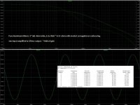
FR curve shows flat HF till 200kHz.
FR curve shows flat HF till 200kHz.
great for driving very specific loads at high voltage swings, but not really what you need here.
I've found that 6K give lowest THD. But yes, load must be 10K.
With lower load impedance THD increases.
In my case, I am going to plug it into my sound card (e-mu 0404) with input impedance 3.3k. I am not sure about DC resistance of it.
Btw, what should I put as Load, impedance or DC resistance?
What do I need here? Will a second stage Cathode Follower help?
If you're going to add a cathode follower, I'd either load the first stage plate with a CCS (highest possible gain) or use a half-mu circuit for the first stage (6dB less gain but half the input capacitance).
The capacitance of the battery to everything else, not the capacitance between the battery terminals. Whatever is inside it, a battery is a lump of conductor and therefore has a capacitance. It is attached to an anode which has had its impedance raised by an unbypassed cathode resistor. Now it may be that the added capacitance does no harm, but a back of envelope calculation could confirm this.mm7 said:DF96 could you explain better what stray capacitance is added? Capacitance of battery is huge and resistance that shunts it is very low.
Calculate the anode impedance. Estimate the battery capacitance - the capacitance of a sphere with the same surface area will be near enough for a first estimate. Calculate the resulting HF rolloff. If the battery is in a chassis clip then its capacitance will be raised.
If you're going to add a cathode follower, I'd either load the first stage plate with a CCS (highest possible gain) or use a half-mu circuit for the first stage (6dB less gain but half the input capacitance).
Hi SY, as I understand, the first stage mu-follower is already CCS (upper part is a cathode follower). Am I right?
Question, do I need a second stage?
The Load will be sound card with input:10K DC resistance, 3.3K impedance (not sure on which frequency though).
If I need a second stage, what topology will be better, Cathode Follower, White Cathode Follower, Aikido, or other?
Hi SY, as I understand, the first stage mu-follower is already CCS (upper part is a cathode follower). Am I right?
Not so much, no. The load to the lower stage can be calculated from the Amos and Birkenshaw formulas (given in "Valve Amplifiers"). You would do much better with a stiff current source (e.g., cascoded bipolars) direct coupled to a cathode follower. The CF can have its operating conditions set separately without the added load of the 6k resistor; best choice there is a high transconductance tube.
Hi DF96,...Calculate the anode impedance. Estimate the battery capacitance - the capacitance of a sphere with the same surface area will be near enough for a first estimate. Calculate the resulting HF rolloff. If the battery is in a chassis clip then its capacitance will be raised.
I see what do you mean. A capacitance between battery and something else, most probable chassis. Or tube electrodes. Right?
Tubes will stick out of chassis. so may be ignored. And capacitance "battery-chassis" will depend on area of projection the battery on chassis. If we turn battery so it faces chassis by one end (area is approximately 1x0.5 "), and it will be distanced from it at 1 - 1.5 inch, what a capacitance will be created?
Calculation gives 0.1 - 0.08 pF accordingly.
I've put this cap between battery and ground. It has no impact from what I can see on AC Analysis graph. Am I correct?
Sorry, my lack of expertise does not allow me to imagine what are you talking aboutNot so much, no. The load to the lower stage can be calculated from the Amos and Birkenshaw formulas (given in "Valve Amplifiers"). You would do much better with a stiff current source (e.g., cascoded bipolars) direct coupled to a cathode follower. The CF can have its operating conditions set separately without the added load of the 6k resistor; best choice there is a high transconductance tube.
 . If you could kindly to draw it?
Here are 3 schematics of preamp:
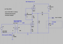
1 - one stage mu-follower
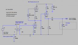
2 - mu-follower + cathode follower
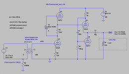
3 - mu-follower + White cathode follower
All have same frequency response ~ 10 - 20kHz, similar THD
and similar output voltage swing
Which schematic is better and why?
1 - one stage mu-follower
2 - mu-follower + cathode follower
3 - mu-follower + White cathode follower
All have same frequency response ~ 10 - 20kHz, similar THD
and similar output voltage swing
Code:
[FONT=Courier New][B]Schematic        THD              Voltage Swing[/B]
MuF              0.002827%        +-2.5V
MuF+CF           0.004341%        +-3.1V
MuF+WCF 0.002524% +-2.9V[/FONT]Attachments
First you need to define 'better'.mm7 said:Which schematic is better and why?
Lower distortion? Lower power consumption? Lower output impedance? Better drive capability? Fewer valves/more valves?
First you need to define 'better'.
Lower distortion? Lower power consumption? Lower output impedance? Better drive capability? Fewer valves/more valves?
Hi DF96,
I mean which is better to amplify a ribbon mic to line level with best sound quality, minimum distortions and noises.
Because I do not have much of expertise it is hard for me to formulate proper requirements. I'll try.
I'd rank requirements this way:
1. overall better sound (I realize that it is subjective, but still, just what do you think)
2. lower output impedance. (my load is 3.3K impedance)
3. better drive capability. (I've calculated for 10KOhm DC load, but sound quality should not degrade too much if preamp is loaded by another load.
If required I can add switchable resistors for balancing to other loads)
4. higher stability
5. lower sensitivity to RF
6. lower sensitivity to PSU noises
... whatever other things you would think are important, place them to whatever rank.
I know almost nothing about microphone preamps, so I am not in a position to judge. It is up to you what you want from it. Bear in mind that some issues are decided by the circuit, some by the construction details, and some by the actual components chosen.
If I had a need to build a mike preamp I think I would find an existing design and copy it, at least as my first stab. I guess before that I would do a lot of reading and thinking so I knew what I was looking for and what the tradeoffs are. Then I would know what I mean by 'better'.
If I had a need to build a mike preamp I think I would find an existing design and copy it, at least as my first stab. I guess before that I would do a lot of reading and thinking so I knew what I was looking for and what the tradeoffs are. Then I would know what I mean by 'better'.
I know almost nothing about microphone preamps, so I am not in a position to judge. It is up to you what you want from it. Bear in mind that some issues are decided by the circuit, some by the construction details, and some by the actual components chosen.
If I had a need to build a mike preamp I think I would find an existing design and copy it, at least as my first stab. I guess before that I would do a lot of reading and thinking so I knew what I was looking for and what the tradeoffs are. Then I would know what I mean by 'better'.
Ribbon mic preamps are just preamps that should amplify very low signal ~3mV from low impedance (~200R) source to line level. They are somewhat similar to LOMC phono preamps but do not have RIAA.
It is very difficult to find existing good ribbon mic preamp on web. I tried.
Initially I've found RCA OP6. Then I read about HiFi phono preamps...
There are some LOMC phono preamps, best of them are based on Mu-follower.
So it was decided to get one as a base, remove RIAA, and possibly modify.
This brought me to these schematics.
Lets turn my question another way - What are main issues are decided by these circuits?
The circuit partly sets the gain, noise and distortion and, apart from the transformer, sets the frequency response. Construction details affect hum/buzz and RF immunity. The key component is the input transformer; other components are less important although valve quality also affects noise.
I always thought that mike preamps had to be somewhat more sensitive than pickup cartridge preamps, but I guess it depends on whether you are doing close miking or just a stereo pair in the audience.
I always thought that mike preamps had to be somewhat more sensitive than pickup cartridge preamps, but I guess it depends on whether you are doing close miking or just a stereo pair in the audience.
could anyone say something bad/good about schematics from post 130? http://www.diyaudio.com/forums/tubes-valves/234937-ribbon-microphone-preamp-13.html#post3510872
could anyone say something bad/good about schematics from post 130? http://www.diyaudio.com/forums/tubes-valves/234937-ribbon-microphone-preamp-13.html#post3510872
Probably none will have enough gain, but the larger issue will likely be the lack of gain controls. We're spoiled by canned music, with its predictable levels, but live sound has huge variations in level which a mic preamp needs to moderate.
All good fortune,
Chris
the third one of course.Here are 3 schematics of preamp:
1 - one stage mu-follower
2 - mu-follower + cathode follower
3 - mu-follower + White cathode follower
All have same frequency response ~ 10 - 20kHz, similar THD
and similar output voltage swing
Which schematic is better and why?Code:[FONT=Courier New][B]Schematic THD Voltage Swing[/B] MuF 0.002827% +-2.5V MuF+CF 0.004341% +-3.1V MuF+WCF 0.002524% +-2.9V[/FONT]
but that only addresses the output buffering issues.
the input side is where its more critical as for your application. as its a tall call for one tube to get 40-60 db of gain from a 15-40ohm impedance source.
now take the third circuit double it, and on the input tale the transformer secondary one lead per grid. then stabilize the quintessential current by tying 470k resistors from grids to ground.
+24 to +32 dbu @ 200 ohms should be your target output.
then use balanced "o" type attenuation on the output to 3.2V p-p.
or go into limiter for dynamic range control, then ADC.
as far as the guy being concerned with gain control, this stage doesn't get it as this stage would be treated like the preamplifier inside condenser mics.
- Status
- Not open for further replies.
- Home
- Amplifiers
- Tubes / Valves
- Ribbon Microphone Preamp